Manuals

kenmore 700 series washer manual

Kenmore 700 Series Washer Manual: A Comprehensive Guide

Navigating Kenmore 700 Series washer care is simplified with readily available PDF manuals‚ offering guides for models like 110․22532 and the Heavy Duty Series 70 (110․92273100)․

Understanding Your Kenmore 700 Series Washer

The Kenmore 700 Series washers represent a blend of durability and functionality‚ commonly found in many households․ Accessing the correct documentation is crucial for optimal performance and longevity․ Several PDF manuals cater specifically to this series‚ including comprehensive guides for models like the 110․22532 washing machine and the robust Heavy Duty Series 70‚ identified by model number 110․92273100․

These manuals aren’t limited to just the 700 Series; resources also exist for related appliances like Kenmore dryers (e․g․‚ the 417 Dryer Tech Sheet) and even older models like Twin Tub washers․ Understanding the specific features of your model‚ as detailed in the manual‚ allows for efficient operation and troubleshooting․ Furthermore‚ resources extend beyond appliance specifics‚ offering location services and geographical coordinate tools‚ though these are ancillary to washer operation․

Model Number Identification

Accurate model number identification is paramount when seeking information about your Kenmore 700 Series washer․ The provided resources highlight the importance of this number‚ frequently referencing models like 110․22532 and the Heavy Duty Series 70‚ specifically 110․92273100․ This number unlocks access to the correct PDF manuals and troubleshooting guides․

Locating the model number typically involves checking a sticker or plate on the appliance itself․ This is often found inside the washer door‚ on the back panel‚ or around the washer’s base․ Having this number readily available streamlines the process of finding relevant documentation‚ ensuring you’re referencing information tailored to your specific Kenmore 700 Series washer․ Remember‚ even within the 700 Series‚ variations exist‚ making the model number essential for accurate support․ Resources also mention unrelated items like Amazon warehouse locations and phone number tracking‚ but the model number remains key for appliance assistance․

Locating the Manual Online (PDF Download)

Finding your Kenmore 700 Series washer manual online is readily achievable through PDF downloads․ Several resources indicate the availability of manuals for specific models‚ such as the 110․22532 and the Heavy Duty Series 70 (110․92273100)․ A quick online search utilizing the full model number will yield numerous results‚ often leading to downloadable PDF versions of the user guide․

These PDFs provide comprehensive information‚ ranging from operating instructions to maintenance procedures and troubleshooting tips․ While searching‚ be mindful of the source to ensure the manual is legitimate and accurate․ Websites offering appliance manuals often host these documents․ Remember that unrelated search results‚ like Amazon warehouse locations or phone tracking services‚ may appear‚ but focusing on appliance-specific sites will expedite the process of securing your Kenmore 700 Series washer’s manual in a convenient‚ downloadable format․

Safety Precautions and Warnings

Prioritizing safety when operating your Kenmore 700 Series washer is paramount․ While specific safety sections within the manual aren’t directly detailed in the provided text snippets‚ general appliance safety guidelines apply․ Always ensure the washer is properly grounded and connected to a suitable power outlet․

Never attempt repairs yourself unless you are qualified to do so; improper repairs can lead to electric shock or machine malfunction․ Keep children and pets away from the washer during operation․ Avoid contact with water if the appliance is not fully disconnected from the power source․ Be cautious when handling detergents and other cleaning agents‚ following the manufacturer’s instructions carefully․ Remember‚ unrelated online searches may yield results for services like phone location tracking or floral diagrams‚ but these are irrelevant to washer safety․ Refer to the complete manual for detailed safety instructions specific to your Kenmore 700 Series model․

Operating Instructions

Effectively utilize your Kenmore 700 Series washer by understanding cycle selections and proper loading techniques‚ as detailed within the comprehensive user manual for optimal results․

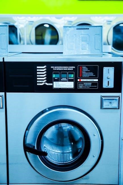
Washer Control Panel Overview

The Kenmore 700 Series washer control panel is designed for intuitive operation‚ though specifics vary slightly by model․ Generally‚ you’ll find a central dial or buttons for cycle selection‚ allowing you to choose from options like Normal‚ Delicates‚ Heavy Duty‚ and Quick Wash․

Temperature controls are typically present‚ enabling adjustments for water temperature – Hot‚ Warm‚ and Cold – to suit different fabric types and soil levels․ Load size adjustments‚ often indicated by buttons or dial positions‚ help optimize water usage based on the amount of laundry․

Additional options may include settings for extra rinse‚ spin speed‚ and soil level․ Some models feature delay start functionality‚ allowing you to schedule washes for later convenience․ Indicator lights clearly display the current cycle status‚ remaining time‚ and any error codes that may arise․ Familiarizing yourself with these controls‚ as outlined in your specific model’s manual‚ ensures efficient and effective washing․

Cycle Selection Guide

Choosing the correct cycle on your Kenmore 700 Series washer is crucial for optimal cleaning and fabric care․ The Normal cycle is ideal for everyday laundry with moderate soil levels․ For delicate items like lingerie or silk‚ the Delicates cycle provides gentle washing․

Heavy Duty tackles heavily soiled items like work clothes or towels‚ utilizing more agitation and a longer wash time․ A Quick Wash cycle is perfect for lightly soiled items needing a fast refresh․ Permanent Press minimizes wrinkles in synthetic fabrics․

Some models offer specialized cycles like Bulky Items for comforters or blankets‚ and Sanitize for disinfecting laundry․ Always consult your washer’s manual for specific cycle details and recommended load sizes; Proper cycle selection extends the life of your clothes and ensures the best possible cleaning performance․

Loading and Unloading the Washer

Proper loading techniques are essential for efficient washing with your Kenmore 700 Series washer․ Avoid overloading‚ as this restricts movement and hinders cleaning․ Distribute items evenly around the agitator or drum to maintain balance․

Before loading‚ empty all pockets and close zippers and hooks to prevent damage․ Separate whites from colors and delicate items from heavier ones․ When unloading‚ remove items promptly to prevent mildew growth․

Be mindful of the washer’s capacity; consult your manual for recommended load sizes․ For bulky items like comforters‚ ensure they are evenly distributed․ Always check the drum for any forgotten items before starting a new cycle․ Careful loading and unloading contribute to optimal performance and garment care․

Detergent Dispenser Usage

The Kenmore 700 Series washer features a designated detergent dispenser‚ typically divided into compartments for pre-wash detergent‚ main wash detergent‚ and fabric softener․ Always use High Efficiency (HE) detergent‚ as standard detergents can create excessive suds and damage the machine․

Refer to your washer’s manual for specific compartment markings and fill levels․ Do not overfill the compartments‚ as this can lead to detergent residue on clothes․ Liquid bleach‚ if used‚ should be diluted with water before adding to the designated bleach dispenser․

Regularly clean the dispenser to prevent clogs and buildup․ Remove the dispenser drawer and rinse thoroughly with warm water․ Proper detergent usage ensures optimal cleaning performance and prolongs the life of your Kenmore 700 Series washer․

Maintenance and Troubleshooting

Maintaining your Kenmore 700 Series washer involves regular cleaning‚ filter checks‚ and addressing error codes for peak performance and longevity‚ as detailed in the manual․

Cleaning the Washer

Regular cleaning is crucial for maintaining the performance and extending the lifespan of your Kenmore 700 Series washer․ The manual likely recommends periodic cleaning cycles using a washer cleaner‚ or a solution of hot water and bleach (always check your manual for specific recommendations regarding bleach use‚ as it can damage certain components)․

Focus on cleaning the drum‚ detergent dispenser‚ and the rubber door seal (if applicable)․ Wipe down the exterior surfaces with a damp cloth and mild detergent․ Pay close attention to areas prone to mildew or mold growth‚ such as the door seal and around the detergent dispenser․

Additionally‚ the manual may detail how to clean the washer’s cabinet and control panel․ Avoid abrasive cleaners‚ as they can scratch the surfaces․ Consistent cleaning prevents buildup of detergent residue‚ fabric softener‚ and mineral deposits‚ ensuring optimal wash results and preventing unpleasant odors․ Following the manual’s guidelines will help keep your Kenmore 700 Series washer in top condition․

Filter Cleaning Procedures

The Kenmore 700 Series washer’s filter requires regular cleaning to prevent clogs and maintain proper drainage․ Your washer manual will detail the exact location of the filter – typically found at the bottom front of the machine‚ behind a small access panel․ Always unplug the washer before attempting to access or clean the filter․

Prepare for potential water spillage by placing towels around the access panel․ Carefully open the panel and unscrew the filter cap‚ allowing any remaining water to drain․ Remove the filter and thoroughly rinse it under running water‚ removing lint‚ debris‚ and small objects like coins or buttons․

Inspect the filter housing for any obstructions and clean it as needed․ Reinstall the filter securely‚ ensuring the cap is tightly closed to prevent leaks․ Refer to your manual for specific instructions and diagrams related to your model․ Regular filter cleaning ensures efficient operation and prevents potential damage to the drain pump․

Common Error Codes and Solutions

Kenmore 700 Series washers utilize error codes to signal malfunctions‚ aiding in troubleshooting․ While specific codes vary by model‚ some are common․ An “F” code often indicates a foreign object or water level issue; check the drain filter and water inlet hoses․ A “LE” code typically signals an unbalanced load – redistribute the clothes or reduce the load size․

Error codes related to the water supply‚ like “E1” or similar‚ suggest issues with the water inlet valve or low water pressure․ Verify the water supply is fully on and the hoses aren’t kinked․ Drainage errors‚ often displayed as “E2” or a similar code‚ point to a clogged drain pump or hose; clean the filter and inspect the hose for obstructions․

Consult your Kenmore 700 Series washer manual for a complete list of error codes and their corresponding solutions․ If an error persists after attempting these fixes‚ professional repair may be necessary to avoid further damage․

Troubleshooting Wash Performance Issues

Poor wash performance with your Kenmore 700 Series washer can stem from several causes․ Insufficient detergent‚ incorrect cycle selection‚ or overloading the machine are frequent culprits․ Ensure you’re using a HE detergent if required and the appropriate amount for your load size․ Verify the water temperature is suitable for the selected cycle; cold water may not effectively clean heavily soiled items․

Clothes remaining wet after the cycle often indicates a drainage problem․ Check the drain hose for kinks or clogs and clean the drain pump filter․ If clothes are still dirty‚ pre-treat stains and consider using a hotter water temperature (if fabric allows)․ An unbalanced load can also hinder cleaning; redistribute items within the drum․

Refer to your Kenmore 700 Series washer manual for specific guidance on addressing wash performance issues․ Regular maintenance‚ like cleaning the dispenser and drum‚ can prevent many problems․

Advanced Features & Repair

Detailed repair guides‚ including belt and water inlet valve procedures‚ are available․ Service manuals for Affinity washers (6000 & 7000 Series) offer advanced insights․

Understanding the Washer’s Components

Delving into the Kenmore 700 Series washer’s internal structure is crucial for effective maintenance and repair․ While specific component details vary by model – such as the 110․22532 or the Heavy Duty Series 70 (110․92273100) – several key parts are common across the range․ These include the drive belt‚ responsible for transferring power from the motor to the drum; the water inlet valve‚ controlling water flow into the machine; and the drain pump‚ which expels used water․

Furthermore‚ understanding the function of the motor itself‚ the control panel assembly‚ and the various sensors is vital․ Accessing service manuals‚ particularly those for Affinity washers (6000 & 7000 Series)‚ provides detailed diagrams and explanations of these components․ Knowing how these parts interact allows for more accurate troubleshooting and targeted repairs‚ ultimately extending the lifespan of your Kenmore 700 Series washer․ Proper identification of each component is the first step towards successful maintenance․

Belt Replacement Guide

Replacing the drive belt on a Kenmore 700 Series washer requires careful attention‚ though it’s a manageable DIY task․ Begin by disconnecting power to the washer – safety first! Accessing the belt typically involves removing the rear panel․ Locate the old belt‚ noting its routing around the motor pulley and the drum;

Carefully remove the old belt‚ then install the new one‚ ensuring it’s properly seated in the grooves of both pulleys․ Double-check the routing against diagrams found in service manuals (referencing models like 110․22532 or 110․92273100 can be helpful)․ Reattach the rear panel and restore power․ Before a full wash cycle‚ manually rotate the drum to confirm the belt is functioning correctly․ A properly installed belt ensures efficient drum rotation and prevents operational issues․ Always consult a detailed manual for your specific model․

Water Inlet Valve Repair

Addressing a faulty water inlet valve on your Kenmore 700 Series washer often resolves issues with water filling․ First‚ disconnect power! Locate the valve – typically at the back of the washer where the water hoses connect․ Disconnect the hoses and carefully remove the old valve‚ noting the wire connections․

Install the new valve‚ ensuring secure hose connections and correct wiring․ A service manual for models like 110․22532 or 110․92273100 will provide specific wiring diagrams․ Before restoring power‚ check for leaks around the hose connections․ Restore power and run a short wash cycle to verify proper water filling․ If the valve continues to malfunction‚ double-check connections and consider professional assistance․ Proper valve function is crucial for efficient washer operation․

Drain Pump Troubleshooting & Replacement

If your Kenmore 700 Series washer isn’t draining‚ the drain pump is a prime suspect․ Begin by disconnecting power! Locate the pump – usually accessible from the rear or bottom panel․ Check for obstructions like lint‚ coins‚ or small articles in the pump housing․ Remove any debris carefully․

To test the pump‚ use a multimeter to check for continuity․ If there’s no continuity‚ the pump needs replacing․ Disconnect the wires and remove the old pump․ Install the new pump‚ ensuring secure connections for both wiring and the drain hose․ Reassemble the washer and run a drain/spin cycle to verify proper operation․ Refer to service manuals for specific model numbers (like 110․22532 or 110․92273100) for detailed diagrams and instructions․ A functioning drain pump is vital for complete water removal․

jacuzzi j300 manual

Jacuzzi J300 Manual: A Comprehensive Guide

Discover detailed instructions, troubleshooting tips, and maintenance schedules for your Jacuzzi J300 spa, ensuring years of relaxing enjoyment and optimal performance․

Welcome to the world of Jacuzzi J300 spas! This series represents a blend of innovative design, powerful hydrotherapy, and user-friendly operation, establishing Jacuzzi as a trusted name since the 1960s – pioneering the first whirlpool with integrated jets and a pump in 1968․ The J300 collection offers a diverse range of models, each designed to deliver a unique wellness experience․

These spas aren’t just about relaxation; they’re about investing in your well-being․ Jacuzzi’s commitment extends beyond initial purchase, offering exceptional customer support and a robust parts availability․ The J300 series incorporates features like infrared and red light technology, enhancing the therapeutic benefits․ This manual will guide you through setup, operation, maintenance, and troubleshooting, ensuring you maximize your spa’s potential for years to come․ Prepare to experience wellness on all sensory levels!

Understanding Your J300 Spa Control Panel

Your Jacuzzi J300’s control panel is the central hub for managing all spa functions․ Familiarizing yourself with its layout is crucial for optimal operation․ The panel typically features buttons for power, temperature adjustment (up/down), jet control, and lighting․ A digital display clearly shows the water temperature and any active settings․

The “On/Color Cycle” button manages the spa’s ambient lighting, allowing you to select from a spectrum of colors or cycle through them automatically․ Error codes, should they appear, provide valuable diagnostic information – refer to the troubleshooting section of this manual for interpretation․ Understanding these controls empowers you to personalize your spa experience and quickly address any operational concerns, ensuring a seamless and enjoyable wellness journey․

Setting Up Your J300 Jacuzzi

Proper installation, filling, and water chemistry balance are essential for a pristine and enjoyable Jacuzzi J300 experience, ensuring longevity and performance․

Initial Spa Setup and Filling

Before your first immersive experience, carefully position your J300 on a level, stable surface capable of supporting its filled weight․ Ensure adequate access for maintenance and electrical connections․ Thoroughly inspect the spa for any shipping damage before proceeding․

Begin filling the spa with a garden hose, using a filter attachment to prevent debris․ Monitor the water level, avoiding overfilling past the recommended fill line․ As the water rises, check for leaks around all fittings and connections․

Once filled, allow the water to warm slightly before adding initial chemicals․ This prevents premature chemical reactions and ensures accurate balancing․ Refer to the water chemistry section for detailed instructions on achieving proper sanitation and pH levels․ Power on the spa after filling and chemical balancing is complete, following all electrical safety precautions․

Water Chemistry Basics for J300 Spas

Maintaining proper water chemistry is crucial for a safe and enjoyable Jacuzzi J300 experience․ Regularly test your water using a reliable test kit or strips, focusing on pH, alkalinity, and sanitizer levels․ Ideal pH should be between 7․2 and 7․8, while total alkalinity should range from 80 to 120 ppm․

Sanitization is vital to eliminate bacteria and algae․ Chlorine or bromine are common sanitizers; follow product instructions carefully for dosage․ Shock the water weekly to oxidize contaminants and maintain sanitizer effectiveness․

Calcium hardness should be between 150-400 ppm to prevent corrosion or scaling․ Adjust chemicals gradually, retesting after each addition․ Improperly balanced water can damage the spa’s components and affect your health․ Consistent monitoring and adjustment are key!

J300 Filter Maintenance and Cleaning

Regular filter maintenance is essential for optimal Jacuzzi J300 performance and water clarity․ Rinse the filter with a garden hose every two weeks to remove debris․ For a deeper clean, soak the filter cartridge overnight in a filter cleaning solution every three months, following the product’s instructions carefully․

Inspect the filter for damage, such as tears or cracks, and replace it if necessary․ A clogged or dirty filter reduces water flow and strains the pump․ The J300 typically uses a pleated filter, designed for efficient filtration․

Proper filter cleaning extends its lifespan and ensures efficient operation․ Always ensure the spa is powered off before removing or cleaning the filter․ A clean filter contributes to healthier, more enjoyable spa experiences!

Operating Your Jacuzzi J300

Effortlessly control your spa’s features, from jet intensity and temperature to lighting, creating a personalized wellness experience with the intuitive J300 control panel․

Powering On and Off Your J300

To initiate operation, locate the main power switch, typically situated near the equipment compartment․ Ensure the switch is in the “Off” position before initial startup or after any maintenance․ Flip the switch to “On” to activate the spa’s systems․ The control panel will illuminate, indicating power is supplied․

For daily use, the J300 can be activated directly from the control panel without using the main power switch, conserving energy․ Simply press the “Power” button on the panel․ To shut down for short periods, use the panel’s “Power” button․

For extended periods or maintenance, always switch off the main power switch to completely isolate the spa from the electrical supply․ This is crucial for safety and prevents unnecessary energy consumption․ Remember to allow the system to fully power down before performing any work․

Adjusting Jet Settings and Intensity

Your Jacuzzi J300 features adjustable jets designed for personalized hydrotherapy․ Locate the jet control buttons on your spa’s control panel․ These buttons typically correspond to different jet zones – for example, neck, shoulder, and foot jets․ Pressing a zone button activates or deactivates those specific jets․

To modify jet intensity within a zone, some J300 models offer adjustable flow controls directly on the jet faceplates․ Rotate these controls to increase or decrease the water pressure․ Experiment to find your preferred level of massage․

Certain models include a “Full Open” position for maximum jet power․ Ensure jets are fully open for optimal performance, especially when troubleshooting low flow issues․ Regularly check and adjust jet settings to enhance your spa experience and target specific muscle groups․

Utilizing the J300 Lighting System

The Jacuzzi J300 boasts a vibrant lighting system to enhance your spa experience․ Access the lighting controls through your spa’s control panel․ Typically, a dedicated “Light” button cycles through various color options․ Press repeatedly to select your desired hue – from calming blues to energetic reds․

Many J300 models feature a “Cycle” or “Color Cycle” mode, which automatically rotates through the available colors, creating a dynamic ambiance․ If the light isn’t functioning, first check the breaker․ If the problem persists, consult the troubleshooting section for error codes․

Dimmer functionality allows you to adjust the brightness of the lights․ Experiment with different settings to create the perfect mood․ Remember to enjoy the visual appeal and relaxation offered by your J300’s integrated lighting system․

Temperature Control and Settings

Maintaining the ideal water temperature is crucial for a comfortable spa experience․ Your Jacuzzi J300’s control panel allows precise temperature adjustments․ Use the “Up” and “Down” arrow buttons to set your desired temperature, typically ranging from 80°F to 104°F (27°C to 40°C)․

The J300 remembers your last set temperature, offering convenience․ However, be mindful of energy consumption and adjust accordingly․ A lower temperature saves energy․ Some models offer programmable schedules, allowing you to pre-set temperatures for different times of the day․

Always allow sufficient time for the water to reach the new temperature after making adjustments․ Monitor the water temperature regularly to ensure it remains within your preferred range, maximizing relaxation and enjoyment․

Troubleshooting Common J300 Issues

Resolve frequent problems like low jet flow, error codes, heating malfunctions, and dimmer light issues with our guide, restoring your Jacuzzi J300’s functionality․

Low Jet Flow Troubleshooting

Experiencing reduced jet pressure in your Jacuzzi J300? Several factors could contribute to this issue․ First, ensure all jets are fully open; sometimes, they can be partially closed, restricting water flow․ Inspect the filter for debris or blockage – a dirty filter significantly reduces circulation․ A clogged filter is a common culprit and requires regular cleaning or replacement․

Next, check the union connections for any obstructions or kinks that might hinder water passage․ Verify the pump is functioning correctly; listen for unusual noises that could indicate a problem․ If the pump seems weak, it might require professional servicing․ Consider the possibility of airlocks within the plumbing system; cycling the jets on and off can sometimes resolve this․

Finally, if the problem persists, consult a qualified Jacuzzi technician to diagnose potential issues with the pump, plumbing, or control system․ Remember patience and systematic checking are key to identifying and resolving low jet flow․

Addressing Error Codes on the J300 Display

Encountering an error code on your Jacuzzi J300’s display? These codes are diagnostic tools indicating a specific system issue․ First, consult your J300 owner’s manual – it contains a comprehensive list of error codes and their corresponding meanings․ Do not attempt repairs without understanding the code’s significance․

Common codes relate to water temperature, heater malfunctions, or sensor problems․ Simple solutions include power cycling the spa – turning it off and on again can sometimes reset the system․ If the error persists, note the exact code and any accompanying symptoms․

Avoid disassembling components yourself; improper handling can void your warranty․ Contact Jacuzzi customer service with the error code information․ Be prepared to describe the circumstances surrounding the error’s appearance․ A technician can guide you through troubleshooting or schedule a service appointment․

J300 Heating System Problems and Solutions

A malfunctioning heater is a common J300 issue․ Initial checks involve verifying the power supply to the heater and ensuring the high limit switch hasn’t tripped․ Inspect the heater element for any signs of corrosion or damage – a visual assessment is crucial; Low water levels can also prevent the heater from functioning correctly; confirm adequate water coverage․

If the heater cycles on and off rapidly, it could indicate a flow issue or a faulty temperature sensor․ Check for obstructions in the filter or plumbing that might restrict water circulation․ Remember to always disconnect power before inspecting electrical components․

For complex problems, such as a completely unresponsive heater, professional assistance is recommended․ Contact Jacuzzi customer support, providing details about the symptoms and any troubleshooting steps taken․ Attempting self-repair on the heating system can be dangerous and may invalidate your warranty․

Troubleshooting Dimmer Light and Color Cycle Issues

If your J300’s lights aren’t responding, begin by checking the control panel settings to ensure the light function is activated․ A common issue involves the on/color cycle button failing to change colors or initiate the cycle․ Try pressing the button firmly and holding it for a few seconds to reset the sequence․

Dim or flickering lights often indicate a loose connection or a failing light assembly․ Carefully inspect the wiring connections to the light, ensuring they are secure and free from corrosion․ If the problem persists, the light itself may need replacement․

Remember to disconnect power before attempting any electrical repairs․ For unresponsive lights or persistent issues, consult the Jacuzzi customer support team, providing a detailed description of the problem and any steps already taken․ Professional diagnosis is recommended for complex electrical concerns․

J300 Spa Maintenance

Maintain your J300’s pristine condition with regular cleaning, winterizing procedures, and proper cover care—extending its lifespan and ensuring continued relaxation․

Regular Cleaning Procedures

Consistent cleaning is vital for a hygienic and enjoyable Jacuzzi J300 experience․ Begin by draining the spa water every 3-4 months, or more frequently with heavy use․ Before draining, activate the ClearRay system (if equipped) to help sanitize the water․ Once drained, thoroughly clean the spa shell using a mild, non-abrasive cleaner specifically designed for acrylic surfaces․

Pay close attention to jets, ensuring they are free from debris and buildup․ Use a soft brush to scrub around the jet nozzles․ The filter should be cleaned or replaced regularly – ideally every two weeks, or as indicated by the filter pressure gauge․ Inspect and clean the headrest pillows and cover as well․ Finally, rinse the spa shell completely before refilling with fresh water, balancing the water chemistry appropriately for optimal water quality and longevity of your J300․

Winterizing Your J300 Jacuzzi

Proper winterization protects your Jacuzzi J300 from freezing temperatures and potential damage․ First, thoroughly drain all water from the plumbing lines by activating the winterize cycle on your control panel, or manually using a blower plug․ Add a winterizing fluid specifically formulated for spas to further displace any remaining water․

Remove the filter and clean it thoroughly before storing it indoors․ Disconnect and drain all pumps, heaters, and jets․ Cover the spa with a secure, insulated winter cover designed for your J300 model․ Regularly inspect the cover throughout the winter to ensure it remains secure and prevents debris accumulation․ Following these steps will ensure a smooth and trouble-free start-up when warmer weather returns․

J300 Cover Care and Maintenance

Maintaining your Jacuzzi J300 cover is crucial for longevity and efficient operation․ Regularly clean the cover with a mild soap and water solution, avoiding harsh chemicals or abrasive cleaners․ Apply a vinyl protectant specifically designed for spa covers to shield against UV damage and prevent cracking․

Inspect the cover periodically for tears, damage, or waterlogging․ Promptly address any issues to prevent further deterioration․ During winter, remove heavy snow accumulation to avoid excessive weight and potential structural damage․ Proper cover care extends the life of your cover, reduces energy costs, and ensures a clean and safe spa experience․ Consider a cover lift for easier removal and storage․

Jacuzzi J300 Safety Information

Prioritize safety with essential guidelines covering electrical precautions, water safety, and child protection, ensuring a secure and enjoyable Jacuzzi J300 experience․

Electrical Safety Precautions

Always ensure your Jacuzzi J300 is properly grounded to prevent electrical shock hazards․ Never operate the spa with a damaged power cord or plug; replace them immediately․ Avoid using extension cords, as they can overheat and pose a risk․ Inspect the electrical connections regularly for any signs of corrosion or damage․

Qualified technicians should perform all electrical installations and repairs․ Do not attempt to modify the electrical system yourself․ Keep the electrical control panel dry and protected from the elements․ Disconnect power before performing any maintenance or cleaning near electrical components․ Adhere to all local electrical codes and regulations․ Remember, water and electricity are a dangerous combination – prioritize safety at all times․ Regular inspections by a certified electrician are highly recommended to maintain a safe operating environment for your J300․

Water Safety Guidelines

Maintain proper water chemistry to prevent bacterial growth and ensure a safe bathing experience․ Regularly test and adjust pH, alkalinity, and sanitizer levels according to the manufacturer’s recommendations․ Never use the spa with water that is cloudy or discolored․ Shower before entering the spa to remove lotions, oils, and other contaminants․ Avoid introducing foreign objects into the water․

Supervise children closely when they are in or near the spa; never leave them unattended․ Limit spa use for pregnant women and individuals with certain medical conditions; consult a physician․ Avoid consuming alcohol before or during spa use, as it can increase the risk of drowsiness and impaired judgment․ Change the water every 3-4 months, or more frequently if needed․ Ensure adequate ventilation to prevent the buildup of chlorine gas․

Child Safety Considerations

Constant, vigilant supervision is paramount when children are near the Jacuzzi J300․ Never leave children unattended, even for a moment, as drowning risk exists․ Implement a safety barrier, such as a self-closing, self-latching gate, around the spa area․ Teach children about spa safety rules, emphasizing the dangers of unsupervised access․ Adjust the water temperature to a safe level for children – generally below 104°F (40°C)․

Consider a safety cover to prevent accidental entry when the spa is not in use․ Educate caregivers about the importance of constant supervision․ Remove any climbable objects near the spa․ Be aware of the potential for hyperthermia in young children, and limit their soak time․ Ensure children understand not to play with the controls or tamper with the equipment․

Jacuzzi Warranty and Customer Support

Explore your J300’s warranty details, locate replacement parts easily, and access Jacuzzi’s exceptional customer service for assistance and support when needed․

Understanding Your J300 Warranty

Your Jacuzzi J300 spa is backed by a comprehensive manufacturer’s warranty, designed to provide peace of mind and protect your investment․ The specific terms and duration of the warranty coverage can vary depending on the model and components․ Generally, the shell is covered for a substantial period, often several years, against blistering, cracking, or fading․

The equipment, including the pump, heater, and control system, also receives warranty coverage, though the length may differ from the shell warranty․ It’s crucial to register your spa promptly after purchase to activate the warranty․ Carefully review the warranty documentation included with your J300 to understand the specific coverage details, exclusions, and claim procedures․

Jacuzzi offers an exceptional commitment to quality and stands behind its products with a dedicated warranty program and a long-term replacement parts availability, ensuring continued enjoyment for years to come․

Contacting Jacuzzi Customer Service

For assistance with your Jacuzzi J300, reaching their customer service team is straightforward․ Jacuzzi provides multiple channels for support, including a dedicated phone line, email support, and an extensive online resource center․ The official Jacuzzi website features a comprehensive FAQ section, troubleshooting guides, and downloadable manuals, potentially resolving your issue quickly․

If you require direct assistance, you can contact Jacuzzi customer service via phone during their business hours; Be prepared to provide your spa’s model number and serial number for efficient support․ When describing a problem, patience and cooperation are appreciated, and a callback may be requested to update you on the resolution progress․

Their commitment to customer satisfaction ensures a responsive and helpful experience, assisting you with any questions or concerns regarding your J300 spa․

Locating Replacement Parts for J300

Maintaining your Jacuzzi J300 often requires replacing parts over time․ Jacuzzi prioritizes long-term support by maintaining a substantial inventory of replacement components, ensuring your spa remains in optimal condition for decades․ Finding the correct parts is simplified through several avenues․

The official Jacuzzi website offers a dedicated parts finder tool, allowing you to search by model number (J300) and specific component․ Authorized Jacuzzi dealers also stock a wide range of replacement parts and can provide expert assistance in identifying the correct items for your needs․

When ordering, having your spa’s serial number readily available is crucial for accurate part identification․ Jacuzzi’s commitment extends beyond initial purchase, guaranteeing accessibility to genuine replacement parts and continued enjoyment of your J300․

Jacuzzi J300 Features & Innovations

Explore the advanced technology, including infrared and red light therapy, and decades of Jacuzzi’s whirlpool innovation within the J300 series for ultimate wellness․

Infrarot- und Rotlicht-Technologie

Jacuzzi is pioneering wellness with its exclusive infrared and red light technology, integrated into select J300 models․ This innovative system goes beyond traditional hydrotherapy, offering a diverse range of health benefits․ Red light therapy is known to potentially stimulate collagen production, improving skin health and reducing the appearance of fine lines․

Infrared light penetrates deeper into tissues, promoting cellular regeneration and potentially easing muscle and joint pain․ The combination of these therapies with the J300’s powerful jets creates a truly immersive and restorative experience․ Users can enjoy enhanced relaxation, improved circulation, and a sense of overall well-being․ Jacuzzi’s commitment to innovation ensures a holistic approach to spa therapy, setting a new standard in home wellness․

History of Jacuzzi Whirlpool Innovation

The Jacuzzi family’s legacy of hydrotherapy began in the 1950s with the development of the first submersible pump for agricultural irrigation․ This ingenuity led to the creation of the first hydrotherapy pump for medical use, assisting a family member’s recovery․ In 1968, Jacuzzi revolutionized relaxation with the introduction of the first self-contained whirlpool bath, featuring integrated jets and a pump – a pivotal moment in wellness history․

For over six decades, Jacuzzi has consistently pushed boundaries in whirlpool technology, focusing on design, performance, and user experience․ This dedication has earned the trust of millions worldwide․ The J300 series builds upon this rich heritage, incorporating advanced features and maintaining Jacuzzi’s commitment to quality and innovation, delivering a superior spa experience․

delonghi esam3300 manual

Delonghi ESAM3300 Manual: A Comprehensive Guide

This manual, sourced from manualsbase (ID: 66028, added 06/23/2020), provides a detailed English guide for the Delonghi ESAM3300, a 25.7MB resource.

The Delonghi ESAM3300 is a popular, fully automatic espresso machine designed for convenient home use. This manual, identified within the manualsbase collection (manuals, manuals_contributions), aims to provide comprehensive instructions for optimal operation. Sourced from the Internet Archive with an item size of 25.7MB and added on June 23, 2020, this guide covers everything from initial setup to advanced features.

Understanding your ESAM3300 will allow you to consistently brew high-quality espresso and enjoy various coffee beverages. This document details the machine’s functions, maintenance procedures, and troubleshooting steps, ensuring a satisfying coffee experience. It’s a valuable resource for both new and experienced users seeking to maximize their machine’s potential.

Key Features and Specifications

The Delonghi ESAM3300, documented within the manualsbase collection (ID 66028, added 06/23/2020), boasts several key features. It’s a bean-to-cup machine, offering freshly ground coffee with adjustable strength and quantity. The integrated grinder ensures optimal flavor extraction. This 25.7MB manual details its user-friendly control panel and automatic functions.

Specifications include a 15-bar pump pressure for rich crema, a 1.8-liter water tank capacity, and a thermoblock heating system for rapid heating. The machine supports both whole beans and pre-ground coffee. Its compact design fits comfortably on most countertops, making it a versatile addition to any kitchen.

Understanding the Control Panel

The Delonghi ESAM3300’s control panel, detailed in manualsbase (ID 66028), features intuitive buttons for brewing, steaming, and accessing decalcification cycles.

Power Button and Indicator Lights

The power button on your Delonghi ESAM3300, as documented in manualsbase (ID: 66028), initiates the machine’s operation. A steady indicator light signifies the machine is on and ready. Flashing lights indicate various stages, such as heating or the need for water.

Understanding these lights is crucial for proper operation. A specific light may illuminate during the brewing process, while another signals when the machine requires descaling. Refer to the full manual, available through manualsbase, for a complete decoding of each indicator light’s meaning. Ignoring these signals could lead to suboptimal performance or potential damage to your appliance. Always consult the manual for clarification.

Function Buttons: Brew, Steam, and Decalcification

The Delonghi ESAM3300, detailed in manualsbase (ID: 66028), features dedicated function buttons for brewing coffee, steaming milk, and initiating the decalcification cycle. The ‘Brew’ button starts the coffee-making process, while the ‘Steam’ button activates the steam wand for milk frothing.

The ‘Decalcification’ button, essential for maintaining optimal performance, initiates the cleaning cycle to remove mineral buildup. Refer to the comprehensive manual available on manualsbase for specific instructions on utilizing each button. Proper use of these functions, as outlined in the documentation, ensures longevity and consistent quality. Ignoring the decalcification cycle can significantly reduce the machine’s lifespan.

Adjusting Coffee Strength and Quantity

The Delonghi ESAM3300, documented on manualsbase (ID: 66028), allows users to customize their coffee experience by adjusting both strength and quantity. Coffee strength is typically controlled via a dial or button, influencing the amount of ground coffee used per brew. Quantity adjustments determine the volume of coffee dispensed, ranging from a single espresso to a longer coffee.

Consult the manual sourced from manualsbase for precise instructions on navigating these settings. Experimentation is encouraged to find your preferred balance. Understanding these controls, as detailed in the 25.7MB resource, unlocks the full potential of the machine, ensuring a perfectly tailored cup every time.

Initial Setup and Preparation

Based on manualsbase (ID 66028, 25.7MB), prepare your Delonghi ESAM3300 by filling the water tank and adding coffee beans before first use;

Filling the Water Tank

The Delonghi ESAM3300’s water tank is crucial for optimal brewing. Locate the tank, typically at the rear or side of the machine, and carefully remove it. Rinse the tank thoroughly with fresh, potable water before each filling to maintain hygiene and prevent scale buildup. Fill the tank with cool, filtered water up to the ‘MAX’ level indicated – avoid overfilling.

Ensure the tank is securely seated back into its designated slot. Improper placement can lead to leaks or brewing issues. Referencing manualsbase (ID 66028, 25.7MB) confirms consistent water quality impacts machine performance and longevity. Regularly check the water level, especially with frequent use, to avoid interruptions during coffee preparation.

Adding Coffee Beans

To enjoy freshly brewed coffee with your Delonghi ESAM3300, locate the bean hopper, usually on top of the machine. Lift the lid and add your favorite whole coffee beans. Avoid overfilling beyond the ‘MAX’ level to prevent jamming of the grinder. Using high-quality beans significantly impacts the final coffee flavor.

Ensure beans are dry and free from any foreign objects. Manualsbase (ID 66028, 25.7MB) highlights that consistent bean quality is key. Experiment with different roasts and origins to discover your preferred taste. Regularly check the bean level and replenish as needed for uninterrupted brewing.

Priming the Machine

Priming the Delonghi ESAM3300 removes air from the system after initial setup or periods of inactivity. Fill the water tank and ensure the machine is powered on. Allow water to flow through the brew group by selecting the brew button without coffee grounds. Repeat this process several times, discarding the water each time, until a steady stream flows consistently.

Manualsbase (ID 66028, 25.7MB) emphasizes this step is crucial for optimal performance. Priming ensures proper water temperature and prevents dry brewing. Continue until no air bubbles are visible in the dispensed water. This initial flush prepares the machine for delivering flavorful espresso.

Brewing Coffee

The Delonghi ESAM3300, detailed in manualsbase (ID 66028, 25.7MB), brews single, double espresso, and long coffees with adjustable strength and quantity settings.

Single Espresso Preparation

To brew a single espresso with your Delonghi ESAM3300 (as detailed in manualsbase, ID 66028), ensure the machine is powered on and primed. Select the ‘Brew’ function on the control panel. Place a suitable espresso cup under the coffee dispenser. The machine, referencing its internal settings, will grind the appropriate amount of beans and tamp them automatically.

The brewing process will commence, delivering approximately 30ml of rich espresso. Adjust coffee strength via the control panel for a customized brew. Refer to the manual for optimal bean type recommendations. Regularly cleaning the brewing unit, as outlined in the maintenance section, ensures consistent espresso quality. Enjoy your freshly brewed single espresso!

Double Espresso Preparation

Preparing a double espresso on your Delonghi ESAM3300 (documented in manualsbase, ID 66028) is similar to a single shot. After powering on and priming the machine, select the ‘Brew’ function. Position a larger cup or two espresso cups beneath the dispenser. The ESAM3300 will automatically grind and tamp a doubled portion of coffee grounds.

This results in approximately 60ml of espresso, ideal for those desiring a stronger coffee experience. Adjust the coffee strength settings on the control panel to personalize your double espresso. Consistent cleaning of the brewing unit, as detailed in the maintenance section, is crucial for optimal performance. Savor your robust double espresso!

Long Coffee Brewing

The Delonghi ESAM3300 (referenced in manualsbase, ID 66028) allows for brewing a ‘Long Coffee’ – a larger, milder coffee similar to an Americano. After the initial setup and priming, select the ‘Brew’ function and then the ‘Long Coffee’ option, if available, or press and hold the brew button. The machine will grind a larger quantity of beans and slowly extract a longer volume of coffee.

This typically yields around 120-150ml. Adjust the coffee strength to your preference. Regular descaling, as outlined in the maintenance section, ensures optimal water flow. Enjoy a relaxed, extended coffee experience with your ESAM3300!

Steaming Milk

The Delonghi ESAM3300 (manualsbase ID 66028) features a steam wand for frothing milk, enabling cappuccinos and lattes. Proper cleaning is essential.

Preparing the Steam Wand

Before steaming milk with your Delonghi ESAM3300 (identified in manualsbase as ID 66028, added June 23, 2020), ensure the steam wand is correctly prepared for optimal performance. Begin by purging the wand to release any condensed water – this prevents dilution of your milk foam. Rotate the dial to the “steam” position, allowing steam to flow briefly into the drip tray.

Always use a stainless steel frothing pitcher, and fill it with cold milk, typically around one-third full. Position the steam wand tip just below the surface of the milk, angling it slightly to create a vortex. This vortex incorporates air, creating the desired microfoam for lattes and cappuccinos. Remember to consult the full manual for detailed instructions and safety guidelines.

Frothing Milk for Cappuccinos and Lattes

Utilizing the prepared steam wand (refer to manualsbase ID 66028, added 2020-06-23, for initial setup), create perfect milk foam for your Delonghi ESAM3300 beverages. For cappuccinos, introduce more air initially, creating a thick, voluminous foam. Submerge the wand slightly deeper to heat the milk without adding further air.

For lattes, focus on creating a velvety microfoam with minimal bubbles. Keep the wand tip near the surface, creating a gentle whirlpool. Monitor the milk temperature – aim for around 140-150°F (60-65°C). Tap the pitcher to remove larger bubbles, and swirl to integrate the foam before pouring. Always prioritize safety as outlined in the complete manual.

Cleaning the Steam Wand

Immediate cleaning of the Delonghi ESAM3300 steam wand, detailed in manualsbase (ID 66028, added 2020-06-23), is crucial. After each use, purge the wand by briefly opening the steam valve to remove residual milk. Wipe the wand thoroughly with a damp cloth to prevent milk buildup.

For a deeper clean, remove the steam wand nozzle (consult the full manual for specifics). Soak the nozzle in warm water, and use a small brush to dislodge any stubborn milk residue. Ensure the wand is completely dry before reattaching. Regular cleaning, as per the manual’s guidelines, maintains hygiene and optimal performance.

Maintenance and Cleaning

Refer to manualsbase (ID 66028, added 06/23/2020) for detailed cleaning instructions. Regular upkeep, including descaling and brewing unit cleaning, ensures longevity.

Daily Cleaning Procedures

Consistent daily cleaning is crucial for maintaining optimal performance and hygiene of your Delonghi ESAM3300. After each use, empty the drip tray and grounds container – resources like manualsbase (ID 66028, added 06/23/2020) detail this. Wipe down the exterior surfaces with a damp cloth to remove any coffee splatters or residue.

The brewing unit should also be briefly rinsed under running water, ensuring no coffee grounds remain. Regularly check and clean the water tank to prevent mineral buildup. These simple steps, outlined in the comprehensive manual available online, will significantly extend the lifespan of your machine and guarantee consistently delicious coffee. Ignoring these procedures can lead to malfunctions and affect coffee quality.

Descaling the Machine

Regular descaling is vital for the longevity of your Delonghi ESAM3300, as mineral deposits from water can impede performance. The manual (sourced from manualsbase, ID 66028, added 06/23/2020) provides detailed instructions. Use a commercially available descaling solution specifically designed for coffee machines, following the product’s guidelines carefully.

The descaling cycle typically involves running the solution through the machine, followed by several rinsing cycles with fresh water. Frequency depends on water hardness; harder water requires more frequent descaling. Ignoring descaling leads to reduced coffee flow, increased energy consumption, and potential damage to internal components. A properly descaled machine ensures optimal brewing temperature and coffee flavor.

Cleaning the Brewing Unit

The Delonghi ESAM3300’s brewing unit requires regular cleaning, as detailed in the manual (manualsbase ID: 66028, added 06/23/2020). This unit is responsible for compacting the coffee grounds and delivering water under pressure. Remove the brewing unit carefully, following the illustrated steps in the manual. Rinse it thoroughly under running water, removing any coffee residue.

Pay close attention to the internal components, ensuring no grounds remain. A clean brewing unit guarantees optimal coffee extraction and prevents clogging. Reinstall the unit securely before operation. Neglecting this cleaning process can lead to weak coffee, inconsistent brewing, and eventual machine malfunction. Regular maintenance extends the machine’s lifespan.

Troubleshooting Common Issues

Refer to the Delonghi ESAM3300 manual (manualsbase ID 66028, added 06/23/2020) for solutions to problems like the machine not powering on or brewing;

Machine Not Turning On

If your Delonghi ESAM3300 fails to power on, first verify the power cord is securely connected to both the machine and a functioning electrical outlet. Consult the comprehensive manual, identified as manualsbase ID 66028 and added on June 23, 2020, for detailed electrical safety precautions.

Check if the outlet itself is providing power by testing it with another device. Ensure the machine’s internal fuse hasn’t blown – the manual provides instructions for accessing and replacing it. A complete power failure might indicate an internal component malfunction, requiring professional service. Remember to always disconnect the machine from the power source before any inspection or maintenance, as detailed within the 25.7MB manual resource.

Coffee Not Brewing Properly

If your Delonghi ESAM3300 isn’t brewing coffee correctly, consult the detailed manual (manualsbase ID 66028, added 06/23/2020) for troubleshooting steps. Common issues include insufficient water in the tank, or beans that are ground too finely or coarsely. Ensure the brewing unit is properly inserted and clean, as outlined in the 25.7MB resource.

A clogged brewing unit or grinder can also cause problems. Refer to the manual’s maintenance section for cleaning instructions. Check the water hardness setting; incorrect settings can affect brewing quality. If the problem persists, descaling the machine, as detailed in the manual, may be necessary to remove mineral buildup impacting water flow.

Steam Wand Not Working

Should the steam wand on your Delonghi ESAM3300 fail to function, the comprehensive manual (manualsbase ID 66028, added 06/23/2020) offers guidance. First, verify sufficient water remains in the tank – steam requires ample supply. Ensure the machine has fully heated up, as indicated by the relevant indicator light. A clogged steam wand is a frequent cause; the 25.7MB resource details cleaning procedures.

Check for mineral buildup, potentially requiring descaling. Confirm the steam function is correctly selected on the control panel. If issues persist, consult the manual’s troubleshooting section for further diagnostics and potential solutions, ensuring safe operation.

Advanced Features and Settings

The Delonghi ESAM3300 manual (manualsbase ID 66028, 25.7MB) details grinder adjustments, water hardness settings, and the automatic shut-off function’s customization.

Adjusting the Grinder Settings

The Delonghi ESAM3300 allows for personalized coffee brewing through adjustable grinder settings. Refer to your machine’s manual (identified as manualsbase ID 66028, a 25.7MB document added on June 23, 2020) for precise instructions. Finer settings yield a stronger, more intense espresso, ideal for those who prefer a robust flavor profile. Conversely, coarser settings produce a milder, less concentrated brew.

Experimentation is key to finding your perfect grind. Begin with the factory default setting and make small adjustments, brewing a test shot after each change. Observe the coffee’s extraction time and taste. If the espresso flows too quickly, tighten the grind. If it flows too slowly, loosen it. Remember to consult the comprehensive guide available through manualsbase for detailed guidance and troubleshooting tips related to grinder calibration.

Water Hardness Setting

Proper water hardness setting is crucial for the longevity of your Delonghi ESAM3300, as detailed in manualsbase document ID 66028 (25.7MB, added 06/23/2020). Hard water causes scale buildup, impacting performance and requiring more frequent descaling. The machine allows you to program the water hardness level based on your local water supply.

Consult your local water authority for hardness information, typically measured in German degrees (dH) or French degrees (fH). Access the machine’s settings menu and navigate to the water hardness option. Input the corresponding value. Correctly setting this parameter ensures the descaling indicator functions accurately, prompting you to descale when necessary, protecting your investment and maintaining optimal brewing conditions.

Automatic Shut-Off Function

The Delonghi ESAM3300, as documented in manualsbase (ID 66028, added 06/23/2020, 25.7MB), features an automatic shut-off function designed for energy conservation and safety. After a period of inactivity – typically around 30 minutes – the machine will automatically power down. This prevents unnecessary energy consumption and reduces the risk of accidental overheating.

This function is a standard safety feature, enhancing user convenience. The machine will retain its programmed settings even after the automatic shut-off. To reactivate, simply press the power button. This feature contributes to the overall efficiency and user-friendliness of the ESAM3300, aligning with modern energy-saving standards.

Safety Precautions

Refer to manualsbase (ID 66028, added 06/23/2020, 25.7MB) for crucial electrical and hot surface warnings, alongside proper usage guidelines for the ESAM3300.

Electrical Safety

Always ensure the Delonghi ESAM3300 is connected to a grounded electrical outlet matching the voltage specified on the machine’s rating label. Never operate the appliance with a damaged cord or plug; immediate replacement is crucial. Avoid using extension cords, as they can pose a safety hazard.

Do not immerse the machine, cord, or plug in water or any other liquid to prevent electric shock. Unplug the ESAM3300 from the outlet when not in use and before cleaning. Refer to manualsbase (ID 66028, added 06/23/2020, 25.7MB) for detailed safety information. Any servicing should be performed by a qualified technician to avoid electrical hazards. Improper use voids the warranty.

Hot Surface Warnings

The Delonghi ESAM3300 operates with high temperatures; exercise extreme caution. The brewing unit, steam wand, and areas surrounding the coffee outlet become very hot during and immediately after use. Avoid touching these components to prevent burns.

Keep children and pets away from the machine while it’s operating or cooling down. Use handles and knobs provided, and always wear appropriate protection if handling hot parts. Refer to manualsbase (ID 66028, added 06/23/2020, 25.7MB) for comprehensive warnings. Allow sufficient cooling time before cleaning or disassembling components. Failure to heed these warnings can result in serious injury.

Proper Usage Guidelines

To ensure optimal performance and longevity of your Delonghi ESAM3300 (sourced from manualsbase, ID 66028, added 06/23/2020 – a 25.7MB resource), always use fresh, cold water in the tank. Employ properly roasted coffee beans, avoiding oily or caramelized varieties. Regularly descale the machine as per the manual’s instructions.

Never operate the machine without water, and always ensure the drip tray is correctly positioned. Do not immerse the appliance in water. Follow the recommended coffee and water ratios for desired strength. Adhering to these guidelines, detailed within the manual, will guarantee a consistently excellent coffee experience and prevent potential damage.

plantronics voyager focus uc user manual

Plantronics Voyager Focus UC User Manual: A Comprehensive Guide

This manual provides detailed instructions for the Plantronics Voyager Focus UC headset‚ covering setup‚ operation‚ troubleshooting‚ and integration with Microsoft 365 and Outlook.

The Plantronics Voyager Focus UC is a premium Bluetooth headset designed for professionals requiring all-day comfort and exceptional audio quality. This headset excels in noisy environments‚ offering superior noise cancellation for focused conversations. It seamlessly integrates with Microsoft Outlook and Microsoft 365‚ streamlining communication and productivity.

Beyond basic call functionality‚ the Voyager Focus UC provides access to partner apps and services like Facebook‚ Dropbox‚ and PayPal. Users can download the Plantronics Hub software for customization and firmware updates‚ ensuring optimal performance. Whether connecting via Bluetooth or USB‚ this headset delivers a reliable and immersive audio experience‚ making it ideal for extended use and demanding workdays.

Unboxing and Components

Upon opening the Plantronics Voyager Focus UC package‚ you should find the headset itself‚ a sleek and professional-looking design built for all-day wear. Included is a charging base‚ essential for maintaining power‚ and a micro-USB charging cable for connecting the base to a power source. A carrying case is also provided‚ protecting the headset during travel or storage.

Additionally‚ the box contains important documentation‚ including a quick start guide and safety information. Some bundles may include a Bluetooth USB dongle for enhanced connectivity with computers; Verify all components are present and undamaged before proceeding with setup. Retain the packaging for potential warranty claims or returns.

Setting Up Your Headset

Begin by charging the Voyager Focus UC and pairing it with your desired devices via Bluetooth or USB for seamless connectivity and optimal performance.

Charging the Headset

To charge your Plantronics Voyager Focus UC‚ connect the provided micro-USB cable to the headset’s charging port and a powered USB source. A full charge typically takes approximately 1.5 hours‚ providing up to 15 hours of talk time. During charging‚ the LED indicator will illuminate.

The light will change color to indicate the charging status: red for charging‚ and green when fully charged. It’s recommended to fully charge the headset before its initial use. You can continue to use the headset while it’s charging‚ but this may extend the total charging time. Avoid using damaged USB cables or power adapters‚ as they could potentially harm the device.

Pairing with Devices (Bluetooth)

To pair the Voyager Focus UC via Bluetooth‚ ensure the headset is in pairing mode. This is typically activated by pressing and holding the power button until the LED flashes blue. Then‚ on your smartphone or computer‚ navigate to the Bluetooth settings and search for available devices.

Select “Plantronics Voyager Focus UC” from the list to initiate pairing. You may be prompted to enter a PIN; if so‚ use “0000”. Once paired‚ the LED will turn solid blue. The headset can remember multiple paired devices‚ allowing seamless switching between them. Remember to disable Bluetooth on unused devices to conserve battery life.

Connecting to Computer via USB

To connect your Voyager Focus UC to a computer using the USB cable‚ simply plug one end into the headset and the other into an available USB port on your computer. The headset will typically be recognized automatically as an audio device.

If not‚ you may need to select it as the default audio input and output device in your computer’s sound settings. This ensures that all audio is routed through the headset. USB connection provides a stable audio link and allows for charging while in use. It’s ideal for voice calls and online meetings requiring high audio quality.

Understanding the Headset Controls

Familiarize yourself with the Voyager Focus UC’s intuitive controls for power‚ volume‚ call management‚ and voice assistant activation for seamless operation.

Power and Volume Controls

The Plantronics Voyager Focus UC features easily accessible power and volume controls designed for convenient operation throughout the day. To power on the headset‚ locate the power button – typically found on the ear cup – and press it until the indicator light illuminates. A short press will also activate voice assistant functionality.

Volume adjustment is managed via dedicated buttons‚ usually positioned alongside the power button. Press the volume up button to increase the audio level and the volume down button to decrease it. These controls allow for quick and precise adjustments without needing to access your connected device’s settings. The headset provides audio prompts to confirm volume changes.

Understanding these basic controls is crucial for maximizing your experience with the Voyager Focus UC‚ ensuring clear communication and comfortable listening.

Call Control Buttons

The Plantronics Voyager Focus UC streamlines call management with intuitive call control buttons conveniently located on the headset. A multi-function button typically handles answering and ending calls – a single press usually answers an incoming call‚ while a longer press often ends the current call.

Dedicated buttons also facilitate muting and unmuting the microphone‚ ensuring privacy when needed. These controls are easily accessible‚ allowing for quick adjustments during conversations. Visual and audio cues confirm mute status.

Mastering these call controls enhances your productivity and professionalism‚ providing seamless control over your communications with the Voyager Focus UC.

Voice Assistant Activation

The Plantronics Voyager Focus UC offers seamless voice assistant integration‚ enhancing hands-free control. Activation is typically achieved through a dedicated button press‚ or by a specific voice command‚ depending on your paired device’s settings (Siri‚ Google Assistant‚ or Cortana).

Once activated‚ you can utilize voice commands to make calls‚ send messages‚ adjust volume‚ or access information without physically interacting with your smartphone or computer.

This feature boosts productivity and convenience‚ allowing you to stay connected and manage tasks efficiently while on the go. Ensure your device’s voice assistant is properly configured for optimal performance.

Optimizing Audio Experience

Achieve superior sound quality with the Voyager Focus UC by properly positioning the microphone‚ adjusting the headset fit‚ and utilizing noise cancellation features.

Microphone Positioning for Clarity

Optimal microphone placement is crucial for clear voice transmission with your Plantronics Voyager Focus UC. The boom arm should be positioned approximately one finger-width away from the corner of your mouth‚ ensuring it captures your voice without picking up excessive breath sounds.

Avoid having the microphone directly in front of your lips‚ as this can lead to distortion. Gently adjust the boom arm for the best balance between voice clarity and background noise reduction. Experiment with slight adjustments to find the sweet spot that works best for your voice and environment.

Remember‚ consistent positioning will yield the most reliable results during calls and recordings.

Adjusting Headset Fit for Comfort

Achieving a comfortable and secure fit is essential for extended wear with your Plantronics Voyager Focus UC. Begin by loosening the headband and earcups. Place the headset over your head‚ ensuring the earcups fully enclose your ears without excessive pressure.

Gradually tighten the headband until the headset feels snug but not constricting. Adjust the earcups to find the optimal angle for a comfortable seal. A proper fit enhances noise cancellation and audio quality.

Experiment with minor adjustments throughout the day to maintain comfort‚ especially during prolonged use.

Noise Cancellation Features & Usage

The Voyager Focus UC boasts advanced noise cancellation‚ crucial for clear calls in busy environments. Activate noise cancellation by pressing the dedicated button on the earcup – a chime confirms activation. This feature minimizes distractions by reducing ambient sounds‚ improving focus and call clarity.

For varying levels of noise‚ experiment with the noise cancellation settings within the Plantronics Hub software. You can choose between high‚ medium‚ and low levels‚ or even an auto mode that adjusts dynamically;

Remember that noise cancellation primarily affects what you hear‚ not what others hear.

Using the Plantronics Hub Software

Plantronics Hub software enables customization of headset settings‚ firmware updates‚ and integration with applications like Microsoft Outlook and Microsoft 365.

Downloading and Installing Plantronics Hub

To begin‚ navigate to the Plantronics website (now Poly) and locate the downloads section. Search for the Plantronics Hub software compatible with your operating system – Windows or macOS. Download the installer file and double-click it to initiate the installation process.

Follow the on-screen prompts‚ accepting the license agreement and choosing your preferred installation directory. The software may request permissions to access certain system features; grant these permissions to ensure full functionality.

Once the installation is complete‚ launch the Plantronics Hub application. You may be prompted to create a Poly account or sign in with an existing one. This account allows you to register your headset and access additional features and support resources.

Customizing Headset Settings

Within Plantronics Hub‚ you can personalize your Voyager Focus UC experience. Explore the settings to adjust audio levels for both incoming calls and media playback‚ optimizing sound for your preferences. Configure the headset’s language settings and enable or disable features like voice assistant activation.

Customize call notification sounds and adjust the sidetone level to control how much of your own voice you hear during calls. Explore options for managing connected devices and setting default audio devices.

The software also allows you to configure OpenVoice Connect integration for seamless connectivity with Microsoft 365‚ enhancing call control within Outlook.

Firmware Updates

Plantronics Hub regularly checks for firmware updates for your Voyager Focus UC headset. Keeping your headset’s firmware current ensures optimal performance‚ stability‚ and access to the latest features and bug fixes. The software will notify you when an update is available.

Before initiating an update‚ ensure your headset is adequately charged and connected to your computer via USB. The update process may take several minutes; avoid disconnecting the headset during this time.

Follow the on-screen prompts within Plantronics Hub to complete the firmware update successfully‚ maintaining peak functionality.

Call Management Features

Effectively manage calls with features like answering‚ ending‚ muting‚ unmuting‚ and transferring‚ alongside the ability to seamlessly conduct conference calls.

Answering and Ending Calls

Answering a call is straightforward: simply press the multi-function button located on the ear cup. A clear audio prompt will confirm the call has been accepted. To reject an incoming call‚ a longer press of the same button is typically required‚ though this may be customizable via the Plantronics Hub software.

Ending a call is equally simple. Press the multi-function button once more during an active call to disconnect. The headset will provide an audible tone indicating the call has ended. Additionally‚ some softphones or computer applications may allow you to answer and end calls directly from your computer‚ bypassing the headset controls – ensuring versatile call handling options.

Muting and Unmuting the Microphone

Maintaining privacy during calls is crucial‚ and the Voyager Focus UC offers a dedicated mute function. A quick press of the designated mute button‚ usually found on the ear cup‚ instantly silences the microphone‚ preventing your voice from being transmitted. A clear audio cue confirms the mute status.

To reactivate the microphone‚ simply press the mute button again. Another audio prompt will indicate that the microphone is now unmuted and ready for use. This feature is particularly useful during conference calls or when needing a moment of private conversation‚ ensuring clear and controlled communication.

Call Transfer and Conference Calls

The Voyager Focus UC streamlines call management‚ supporting both call transfer and conference call functionalities. Transferring a call typically involves placing the current call on hold and then dialing the intended recipient. Once connected‚ you can seamlessly transfer the active call to the new party.

For conference calls‚ the headset allows you to merge multiple callers into a single conversation. Initiate the process through your connected device (computer or smartphone) using the appropriate conferencing application. The Voyager Focus UC delivers clear audio for all participants‚ enhancing collaboration and productivity during multi-party discussions.

Connectivity and Integration

The Voyager Focus UC offers seamless connectivity‚ integrating with Microsoft Outlook and 365‚ plus various partner apps for enhanced communication and workflow.

Microsoft Outlook Integration

The Plantronics Voyager Focus UC streamlines your workday with robust Microsoft Outlook integration. Connecting to Outlook via Microsoft 365 allows for effortless access to your emails‚ calendar‚ and other essential communication tools directly through the headset. This integration enhances productivity by providing call control features within the Outlook interface‚ enabling you to answer‚ end‚ and mute calls without switching applications.

Furthermore‚ the Plantronics Hub software facilitates a smooth setup process‚ ensuring a stable and reliable connection. You can view call history and manage contacts directly within Outlook‚ creating a unified communication experience. This feature is particularly beneficial for professionals who heavily rely on Outlook for daily tasks and require seamless call management.

Connecting with Microsoft 365

Seamless integration with Microsoft 365 unlocks the full potential of your Plantronics Voyager Focus UC headset. This connection enables access to a suite of productivity tools‚ including Outlook email‚ calendar functionalities‚ and Office Online applications like Word‚ Excel‚ and PowerPoint. Utilizing Microsoft 365‚ users can experience enhanced call control directly within these applications‚ boosting efficiency.

The Plantronics Hub software simplifies the connection process‚ ensuring a stable and secure link. Accessing your Microsoft 365 account through the headset allows for streamlined communication and collaboration. Get more done by connecting to partner apps and services‚ enhancing your workflow and overall user experience with this powerful integration.

Compatibility with Other Applications

The Plantronics Voyager Focus UC isn’t limited to Microsoft’s ecosystem; it boasts broad compatibility with numerous other applications. Users can seamlessly connect to popular services like Facebook‚ Dropbox‚ PayPal‚ and Uber‚ enhancing productivity across various platforms. Integration with tools like Boomerang further streamlines workflow management.

Beyond these‚ the headset generally functions with any application supporting Bluetooth or USB audio connectivity. This versatility makes it ideal for diverse work environments and communication needs. The Plantronics Hub software aids in ensuring optimal performance and compatibility‚ offering a consistent experience regardless of the application used.

Troubleshooting Common Issues

This section addresses frequent problems like audio disruptions (static‚ no sound)‚ Bluetooth connectivity failures‚ and charging difficulties with the Voyager Focus UC.

Audio Problems (No Sound‚ Static)

Experiencing audio issues with your Plantronics Voyager Focus UC? First‚ verify the volume is appropriately adjusted on both the headset and the connected device. Ensure the correct audio output device is selected within your computer’s sound settings – sometimes it defaults incorrectly.

If static is present‚ try moving away from potential sources of interference like microwaves or other wireless devices. A simple headset reset can often resolve minor glitches; consult the ‘Resetting the Headset’ section for instructions. Check for updated drivers for your Bluetooth adapter or USB connection. Finally‚ test with a different audio source to isolate whether the problem lies with the headset or the original source.

Bluetooth Connection Issues

Troubleshooting Bluetooth connectivity with your Voyager Focus UC? Begin by confirming Bluetooth is enabled on both the headset and your pairing device. Ensure the headset isn’t already connected to another device‚ as it can only maintain one active Bluetooth connection at a time.

If pairing fails‚ try ‘forgetting’ the headset from your device’s Bluetooth settings and then re-initiating the pairing process. Proximity matters – keep the headset close to the device during pairing. Restarting both the headset and the device can often resolve connection conflicts. Check for Bluetooth driver updates on your computer for optimal performance.

Headset Not Charging

Experiencing issues charging your Plantronics Voyager Focus UC? First‚ verify the charging cable is securely connected to both the headset and a functioning power source. Try a different USB port or wall adapter to rule out a power supply problem. Ensure the charging contacts on both the headset and the charging cable are clean and free of debris.

A full charge can take time; allow ample time for charging. If the headset still doesn’t charge‚ attempt a factory reset (consult the full manual for instructions). Contact Plantronics support if the problem persists‚ as it may indicate a battery or hardware fault.

Care and Maintenance

Regular cleaning with a soft cloth and proper storage will maximize the lifespan and performance of your Plantronics Voyager Focus UC headset.

Cleaning the Headset

To ensure optimal hygiene and performance‚ regularly clean your Plantronics Voyager Focus UC headset. Begin by disconnecting the headset from any connected devices. Use a soft‚ slightly damp (not wet!) cloth to gently wipe down the earcups‚ headband‚ and microphone boom. Avoid using harsh chemicals‚ abrasive cleaners‚ or solvents‚ as these can damage the headset’s finish and components.

For stubborn grime‚ a small amount of isopropyl alcohol can be applied to the cloth‚ but always test on an inconspicuous area first. Pay particular attention to areas that come into direct contact with skin‚ such as the earcups. Ensure the headset is completely dry before reconnecting or storing it. Regular cleaning contributes to a comfortable and sanitary user experience‚ prolonging the life of your valuable communication tool.

Storing the Headset

Proper storage is crucial for maintaining the longevity of your Plantronics Voyager Focus UC headset. When not in use‚ store the headset in a cool‚ dry place‚ away from direct sunlight and extreme temperatures. Ideally‚ utilize the included carrying case to protect it from dust‚ impacts‚ and potential damage. Avoid storing the headset in areas with high humidity‚ as this can affect the internal electronics.

Do not coil the charging cable tightly‚ as this can cause internal damage over time. A loose loop is preferable. Ensure the headset is fully powered off before storage. Following these simple guidelines will help preserve the headset’s functionality and appearance for years to come.

Battery Life and Replacement

The Plantronics Voyager Focus UC boasts an impressive battery life‚ offering up to 15 hours of talk time on a single charge. Standby time can extend up to 20 days. Battery performance naturally degrades over time with usage and charging cycles. If you notice a significant reduction in battery life‚ consider optimizing settings within the Plantronics Hub software.

Battery replacement should only be performed by authorized service personnel. Attempting to replace the battery yourself may void the warranty and potentially damage the headset. Contact Plantronics support for information regarding battery replacement options and authorized service centers.

agilent 6890n manual

Agilent 6890N Manual: A Comprehensive Guide

This comprehensive guide details the Agilent 6890N Gas Chromatograph, offering service and troubleshooting information, alongside preventative maintenance schedules and repair guidance.

The Agilent 6890N Gas Chromatograph represents a robust and reliable analytical instrument widely utilized in various scientific disciplines. This manual serves as a crucial resource for personnel involved in the operation, maintenance, and service of this system. It’s designed to aid users in understanding the instrument’s functionalities and addressing potential issues effectively.

Agilent initially provided guaranteed support through July 31, 2015, however, accessories remain available. This service manual details common troubleshooting tasks and provides essential information before contacting Agilent for assistance. Understanding its contents ensures optimal performance and longevity of the 6890N GC, facilitating accurate and dependable analytical results.

Understanding the Service Manual

This service manual for the Agilent 6890N Gas Chromatograph is a vital tool for qualified personnel performing instrument upkeep and repair. It encompasses detailed procedures for preventative maintenance, troubleshooting common errors, and advanced diagnostics. Users will find guidance on interpreting error codes and performing leak detection.

The manual also outlines procedures for electronic component diagnostics and software/firmware updates. It’s crucial to observe all warnings detailed within, ensuring safe operation during all phases of service. Proper utilization of this resource minimizes downtime and maximizes the instrument’s analytical capabilities, referencing the 6890 Basic Troubleshooting manual when needed.

Key Features and Specifications

The 6890N boasts robust gas chromatography principles, diverse system components, and reliable performance, detailed within this manual for optimal operation and service.

Gas Chromatography Principles

Gas chromatography (GC) separates and analyzes volatile substances by vaporizing a sample and passing it through a stationary phase. The Agilent 6890N leverages this principle, utilizing a carrier gas to transport analytes through a column;

Different compounds interact differently with the stationary phase, causing them to elute at varying times, enabling identification and quantification. This manual details how the 6890N precisely controls temperature programming, injection techniques, and detector responses to achieve optimal separation. Understanding these core principles is crucial for effective operation, troubleshooting, and maximizing the instrument’s analytical capabilities. Proper GC technique ensures accurate and reproducible results, vital for research and quality control applications.

6890N System Components

The Agilent 6890N GC comprises several key components working in harmony. These include the gas supply system, inlet(s) – such as split/splitless or on-column injectors – and the column itself, where separation occurs. A temperature-controlled oven houses the column, optimizing analyte elution.

Detectors, like Flame Ionization Detectors (FID) or Mass Spectrometers (MS), signal compound presence. The electronic control unit (ECU) manages all functions, and the data system acquires and processes results. This manual provides detailed schematics and descriptions of each component, aiding in service and repair. Understanding these interactions is vital for efficient operation and troubleshooting.

Installation and Setup

Proper installation requires careful unpacking, inspection, and adherence to gas supply requirements, alongside precise column installation procedures as detailed in this manual.

Unpacking and Initial Inspection

Upon receiving your Agilent 6890N, thoroughly inspect the shipping container for any signs of damage during transit. Carefully unpack all components, cross-referencing them with the packing list to ensure everything is accounted for.

Visually examine each item for physical damage, such as dents, scratches, or broken parts. Document any discrepancies immediately and contact Agilent Technologies for assistance. Retain all packaging materials until the instrument is fully operational and you are satisfied with its condition.

Verify the instrument’s voltage setting matches your local power supply before proceeding with installation. A detailed inspection prevents potential issues and ensures a smooth setup process, safeguarding your investment.

Gas Supply Requirements

The Agilent 6890N GC requires high-purity carrier, fuel, and auxiliary gases for optimal performance. Carrier gas, typically helium, hydrogen, or nitrogen, must be at least 99.999% pure. Fuel gas, used for flame detectors, necessitates a purity of 99.999% for both hydrogen and air.

Gas cylinders should be equipped with appropriate regulators and fittings, ensuring compatibility with the instrument’s gas inlet connections. Maintain stable gas pressures as specified in the instrument’s specifications. Proper gas supply is crucial for accurate and reliable analytical results, preventing detector instability and baseline drift.

Column Installation Procedures

Proper column installation is vital for optimal Agilent 6890N GC performance. Begin by carefully inspecting the column for any physical damage before installation. Gently insert the column into the injector, ensuring it’s seated correctly to prevent leaks.

Follow the manufacturer’s recommendations for column conditioning, typically involving a slow temperature ramp to avoid damaging the stationary phase. Securely tighten the column nut, avoiding over-tightening. Verify a leak-free connection using an electronic leak detector. Incorrect installation can lead to peak broadening, ghost peaks, and reduced column lifespan.

Routine Maintenance Procedures

Regular maintenance ensures reliable 6890N operation. This includes scheduled checks of gas flow, detector performance, and preventative measures for optimal functionality.

Preventative Maintenance Schedule

Establishing a consistent preventative maintenance schedule is crucial for maximizing the lifespan and performance of your Agilent 6890N Gas Chromatograph. This schedule should encompass daily, weekly, monthly, and annual checks. Daily routines involve visual inspections for leaks and ensuring proper gas supply.

Weekly tasks include verifying detector cleanliness and confirming gas flow rates are within specified parameters. Monthly procedures should incorporate a thorough examination of the injector system and column condition. Annually, a comprehensive system check, potentially involving an Agilent service representative, is recommended.

Adhering to this schedule minimizes downtime, reduces the risk of unexpected failures, and ensures accurate and reliable analytical results. Detailed instructions for each task are outlined within the service manual.

Detector Performance Checks

Regular detector performance checks are vital for maintaining the accuracy and sensitivity of your Agilent 6890N GC. These checks should include sensitivity testing, using appropriate standards to verify response factors. Baseline noise should be monitored to identify potential issues with electronic components or contamination.

Peak shape analysis is also crucial; distorted peaks can indicate column degradation or improper gas flow; Response time verification ensures the detector is reacting quickly and accurately to analyte elution. The manual provides detailed procedures for each test.

Consistent monitoring and documentation of these parameters allow for early detection of performance drift, enabling timely corrective actions and minimizing analytical errors.

Gas Flow Verification

Accurate gas flow verification is essential for optimal Agilent 6890N GC performance. Regularly check carrier, detector, and auxiliary gas flows using calibrated flow meters or the instrument’s electronic flow controllers. Compare measured values against the settings specified in your method.

Any discrepancies could indicate leaks, regulator malfunctions, or restrictions within the gas lines. The manual details procedures for leak testing using electronic leak detectors or soap solutions. Ensure all connections are tight and tubing is free from kinks or damage.

Consistent gas flow ensures reproducible retention times and peak shapes, contributing to reliable analytical results.

Troubleshooting Common Issues

This section provides guidance on interpreting error codes, addressing leak detection, and resolving common injector problems within the Agilent 6890N GC.

Error Code Interpretation

Understanding error codes is crucial for efficient troubleshooting of the Agilent 6890N. The service manual details a comprehensive list, categorizing issues by severity and component. These codes pinpoint specific malfunctions, ranging from gas supply problems to detector failures or electronic component errors.

Each code is accompanied by a description of the potential cause and recommended corrective actions. Users should consult the manual’s dedicated error code table to accurately diagnose the problem. Ignoring error codes can lead to further damage or inaccurate results. Proper interpretation allows for targeted repairs, minimizing downtime and ensuring optimal instrument performance. Agilent emphasizes utilizing these codes before contacting service.

Leak Detection and Repair

Leak detection is paramount for maintaining the Agilent 6890N’s performance and ensuring safety. The service manual outlines procedures using electronic leak detectors and soap solutions to identify leaks in gas lines, fittings, and the column connection. Agilent recommends regular checks, especially after column installation or component replacement.

Repairing leaks typically involves tightening fittings, replacing ferrules, or resealing connections. Always de-pressurize the system before attempting any repairs. The manual provides detailed diagrams and instructions for disassembling and reassembling components. If leaks persist, consult the manual for specific troubleshooting steps or contact Agilent service for assistance. Ignoring leaks can compromise analysis and pose a hazard.

Injector Problems and Solutions

Injector issues commonly involve leaks, clogging, or poor peak shape. The Agilent 6890N manual details troubleshooting steps for each scenario. Leaks often require tightening fittings or replacing O-rings and ferrules. Clogging can result from sample matrix buildup, necessitating thorough cleaning with appropriate solvents, as outlined in the service manual.

Poor peak shape may indicate discrimination or degradation. The manual suggests checking the injection volume, syringe calibration, and liner condition. If problems persist, consult the 6890 Basic Troubleshooting manual or contact Agilent. Proper injector maintenance, including regular cleaning and liner replacement, is crucial for optimal performance and reliable results.

Advanced Troubleshooting & Service

Advanced service involves electronic component diagnostics, software/firmware updates, and utilizing Agilent’s support resources for complex issues and repair procedures.

Electronic Component Diagnostics

Effective electronic component diagnostics are crucial for pinpointing the root cause of complex Agilent 6890N issues. This process often requires a systematic approach, utilizing schematics and specialized testing equipment. Technicians must carefully examine circuit boards, power supplies, and signal pathways to identify faulty components.

Troubleshooting involves checking voltages, resistances, and signal integrity at various test points. Agilent provides detailed documentation outlining component locations and expected values. Furthermore, understanding the interplay between different electronic modules is essential for accurate diagnosis. Proper grounding and shielding are also vital considerations during this phase of service.

Component replacement should only be performed by qualified personnel, adhering to ESD precautions to prevent further damage. Always verify the correct part number and specifications before installation.

Software and Firmware Updates

Maintaining up-to-date software and firmware is vital for optimal Agilent 6890N performance and security. Agilent regularly releases updates to address bugs, enhance functionality, and improve compatibility with new accessories. These updates can be downloaded from the Agilent support website or installed via a network connection.

Before initiating an update, it’s crucial to back up existing data and configurations to prevent data loss. Carefully follow the installation instructions provided with the update package. Interrupting the update process can render the instrument inoperable, requiring service intervention.

Firmware updates often require a specific procedure and may necessitate a bootable USB drive. Always verify the update’s compatibility with your 6890N configuration.

Agilent Service Support Information

Agilent Technologies provides comprehensive service and support for the 6890N Gas Chromatograph, even with discontinued support for certain products. For immediate assistance, consult the Agilent website for frequently asked questions, knowledge base articles, and online troubleshooting guides.

To request on-site service, contact your local Agilent representative or utilize the online service request form. When contacting support, have your instrument’s serial number and a detailed description of the issue readily available.

Agilent offers various service agreements tailored to your needs, ensuring proactive maintenance and minimizing downtime. Remember that guaranteed support ended July 31, 2015, but accessories remain available.

Safety Precautions and Warnings

Observe all warnings within the manual and on the instrument during operation, service, and repair to prevent hazards and ensure safe usage.

Electrical Safety Guidelines

Prioritize electrical safety when working with the Agilent 6890N. Always disconnect the instrument from the power source before performing any service or repair procedures involving electrical components.

Ensure proper grounding to prevent electrical shock hazards. Never operate the instrument with damaged power cords or plugs. Regularly inspect all electrical connections for wear and tear, replacing them as needed.

Qualified personnel should handle all electrical work, adhering to local and national electrical codes. Avoid contact with live circuits, and use insulated tools when working near electrical components. Be aware of high voltage areas within the instrument and exercise extreme caution.

Handling Hazardous Materials

The Agilent 6890N may utilize or come into contact with hazardous materials, including carrier gases, solvents, and samples. Always wear appropriate personal protective equipment (PPE), such as gloves, eye protection, and lab coats, when handling these substances.

Ensure adequate ventilation to avoid inhalation of harmful vapors. Dispose of waste materials according to local regulations and safety guidelines. Familiarize yourself with the Safety Data Sheets (SDS) for all chemicals used with the instrument.

In case of spills or leaks, follow established emergency procedures and use appropriate cleanup materials. Never mix incompatible chemicals, and store hazardous materials in designated, properly labeled containers.

Early Maintenance Feedback (EMF)

Agilent’s Early Maintenance Feedback (EMF) system proactively monitors instrument performance, alerting users to potential issues before they escalate into major failures. This feature, detailed within the 6890 user manual, provides valuable insights into component health and operational status.

EMF notifications help schedule preventative maintenance, minimizing downtime and extending the instrument’s lifespan. By addressing minor problems early, costly repairs can be avoided. Users can access EMF data through the instrument’s software interface, enabling informed decision-making regarding service needs.

Discontinued Support & Upgrade Paths

Agilent guaranteed support for the 6890N ended July 31, 2015, but accessories remain available; the 7890A GC is recommended as a replacement.

7890A GC System as a Replacement

Considering the discontinuation of full support for the 6890N, the Agilent 7890A Gas Chromatograph emerges as a logical and highly capable replacement option. This system builds upon the foundation of the 6890 series, incorporating significant advancements in technology and performance.

The 7890A offers enhanced sensitivity, improved data quality, and increased throughput, allowing for more efficient and reliable analyses. It maintains compatibility with many existing 6890N columns and accessories, simplifying the upgrade process and minimizing additional costs. Furthermore, the 7890A benefits from ongoing Agilent support, ensuring long-term reliability and access to the latest software and firmware updates. Transitioning to the 7890A provides a pathway to continued productivity and analytical excellence.

Availability of Accessories

Despite the phased-out support for the Agilent 6890N GC, a substantial range of accessories remains available for purchase, ensuring continued operation and maintenance of existing instruments. These include essential components like columns, liners, septa, gas purification filters, and detector parts.

Agilent continues to manufacture and stock many commonly used accessories, allowing laboratories to perform necessary repairs and preventative maintenance. While some specialized or older parts may have limited availability, Agilent’s online catalog and customer support teams can assist in sourcing suitable alternatives. Maintaining access to these accessories extends the lifespan and usability of the 6890N, providing a cost-effective solution for ongoing analytical needs.

viper 7756v manual

The Razer Viper 7756V is a high-performance gaming mouse, celebrated for its lightweight design and advanced features, offering a competitive edge to players.

Overview of the Razer Viper Series

The Razer Viper series represents Razer’s commitment to creating top-tier gaming mice, consistently pushing boundaries in speed, accuracy, and ergonomic design. Originating with the initial Viper, the series quickly gained recognition among esports professionals and enthusiasts alike. Subsequent iterations, like the Viper Mini, Viper Ultimate, and now the Viper 7756V, have refined the formula, catering to diverse hand sizes and grip preferences.

These mice are characterized by their lightweight construction, utilizing high-grade materials to minimize weight without sacrificing durability. Razer Vipers consistently feature cutting-edge optical sensors and Razer’s HyperSpeed Wireless technology, ensuring minimal latency and precise tracking. The series embodies a sleek, minimalist aesthetic, focusing on performance above all else.

What is the Razer Viper 7756V?

The Razer Viper 7756V is a cutting-edge wireless gaming mouse designed for competitive play. Weighing in at a remarkably light weight, it prioritizes swift, controlled movements, enhancing reaction time during intense gaming sessions. It boasts Razer’s advanced optical sensor for exceptional tracking accuracy and utilizes HyperSpeed Wireless technology for a lag-free experience.

This model features customizable buttons, adjustable DPI settings, and vibrant Razer Chroma RGB lighting effects, allowing for personalized control and aesthetics. The Viper 7756V aims to deliver a seamless blend of performance, comfort, and customization, appealing to both casual gamers and esports professionals seeking a competitive advantage.

Unboxing and Components

The Razer Viper 7756V package includes the mouse itself, a USB-C cable for wired connectivity, and essential documentation for setup and usage.

Package Contents

Upon unboxing the Razer Viper 7756V, users will discover a carefully arranged set of components designed to enhance the gaming experience. The core inclusion is, naturally, the Razer Viper 7756V gaming mouse itself, boasting a sleek and ergonomic design. Alongside the mouse, a high-quality USB-C cable is provided, facilitating both data transfer and charging when used wirelessly.

Furthermore, the package contains a quick start guide, offering essential instructions for initial setup and configuration. A booklet detailing safety information and warranty details is also included, ensuring user awareness and protection. Finally, Razer often includes signature stickers for personalization, allowing gamers to customize their setup with the iconic Razer logo.

Physical Features and Design

The Razer Viper 7756V showcases a predominantly black color scheme, exuding a modern and stealthy aesthetic. Its symmetrical form factor caters to both right-handed and left-handed gamers, promoting versatility and comfort. The mouse features a smooth, matte finish, providing a secure grip during intense gaming sessions. Constructed with durable materials, the Viper 7756V balances lightweight construction with robust build quality.

The design prioritizes minimizing weight without compromising structural integrity, enabling swift and precise movements. Subtle Razer Chroma RGB lighting accents add a customizable visual flair, enhancing the overall gaming setup’s aesthetic appeal.

Weight and Dimensions

The Razer Viper 7756V is engineered for speed and agility, boasting a remarkably lightweight design. Weighing in at just 69 grams, it facilitates faster, more controlled movements, crucial for competitive gaming. This reduced weight minimizes fatigue during extended play sessions. Its dimensions are carefully considered to provide a comfortable and ergonomic experience for a wide range of hand sizes.

The precise measurements contribute to its balanced feel and maneuverability. This lightweight profile, combined with its compact size, makes the Viper 7756V a formidable tool for any gamer.

Ergonomics and Grip Styles

The Razer Viper 7756V features a symmetrical form factor, catering to both right-handed and left-handed gamers, promoting inclusivity and comfort. This design allows for versatile grip styles, including palm, claw, and fingertip grips, adapting to individual preferences. The mouse’s shape encourages a natural hand position, reducing strain during prolonged use.

Its contours are designed to provide a secure and comfortable hold, enhancing control and precision. The lightweight build further contributes to ergonomic comfort, minimizing fatigue and maximizing performance for all grip styles.

Setting Up Your Razer Viper 7756V

Initial setup involves installing Razer Synapse software and connecting the mouse, either via a wired or wireless HyperSpeed connection for optimal performance.

Software Installation (Razer Synapse)

Razer Synapse is essential for unlocking the full potential of your Viper 7756V. Download the latest version from the official Razer website and follow the on-screen instructions for installation. During setup, you’ll likely need to create a Razer account or log in to an existing one.

Synapse allows complete customization, including button remapping, DPI adjustments, and lighting control via Razer Chroma. The software also manages on-board profiles, enabling you to save personalized settings directly to the mouse’s memory. Regularly check for Synapse updates to ensure compatibility and access to new features. Proper installation guarantees seamless integration and optimal performance.

Connecting the Mouse

The Razer Viper 7756V offers both wired and wireless connectivity options for versatile use. For a wired connection, simply plug the included USB cable into an available port on your computer; the mouse will be instantly recognized. To utilize the wireless HyperSpeed functionality, insert the USB dongle into a USB port.

Ensure the mouse is powered on via the switch on its underside. Razer Synapse will guide you through the pairing process. Wireless offers freedom of movement, while wired provides a stable, lag-free experience. Choose the connection method that best suits your gaming style.

Wired Connection

Establishing a wired connection with the Razer Viper 7756V is straightforward. Locate the USB-A to USB-C cable included in the package. Plug the USB-A end into an available USB port on your gaming PC or laptop. Connect the USB-C end securely into the port located on the front of the Viper 7756V mouse.

Upon connection, the mouse should be immediately recognized by your operating system. No additional drivers are typically required for basic functionality. A wired connection ensures a stable, low-latency experience, ideal for competitive gaming where precision and responsiveness are paramount.

Wireless Connection (HyperSpeed)

To utilize the Razer HyperSpeed wireless technology, first, ensure the USB receiver dongle is plugged into a USB port on your PC. Power on the Viper 7756V by pressing the power button located on the underside. The mouse will automatically attempt to pair with the receiver. A successful connection is indicated by a solid LED light on the mouse.

Razer HyperSpeed provides a near-latency-free wireless experience, rivaling wired connections. For optimal performance, keep the receiver within close proximity to the mouse and minimize wireless interference from other devices.

Customization and Configuration

Razer Synapse software unlocks extensive customization options for the Viper 7756V, including button assignments, DPI adjustments, and vibrant Chroma lighting effects.

Button Mapping

The Razer Viper 7756V offers comprehensive button mapping capabilities through Razer Synapse. Users can reassign functions to each button, tailoring the mouse to their specific gaming needs and preferences. This includes assigning complex macros, media controls, or keyboard functions.

Synapse allows for profile creation, enabling different button configurations for various games or applications. The intuitive interface simplifies the process, allowing for quick and easy adjustments. Furthermore, on-board memory allows saving these customized profiles directly to the mouse, ensuring consistent performance across different systems without needing Synapse installed.

DPI Settings and Calibration

The Razer Viper 7756V provides extensive control over DPI (dots per inch) settings via Razer Synapse. Users can precisely adjust the mouse’s sensitivity, ranging from a low DPI for precise aiming to a high DPI for rapid movements. Multiple DPI stages are configurable, allowing for on-the-fly sensitivity switching during gameplay;

Synapse also offers surface calibration, optimizing sensor performance based on the mousepad being used. This ensures accurate tracking and minimizes unwanted acceleration or smoothing. Fine-tuning options allow users to customize polling rate and acceleration curves, further refining the mouse’s responsiveness to individual preferences.

Lighting Effects (Razer Chroma)

The Razer Viper 7756V boasts full Razer Chroma RGB lighting customization through Razer Synapse. Users can select from a spectrum of 16.8 million colors and a variety of dynamic lighting effects, including static, breathing, and wave. Synchronization with other Chroma-enabled devices is possible, creating a unified lighting ecosystem.

Synapse allows for per-profile lighting configurations, enabling distinct visual cues for different games or applications. Game integrations trigger reactive lighting effects based on in-game events, enhancing immersion. Users can also import or create custom lighting profiles, tailoring the aesthetic to their preferences.

Advanced Features

The Razer Viper 7756V incorporates a cutting-edge optical sensor, Razer HyperSpeed Wireless technology, and on-board memory for customized profiles and settings.

Optical Sensors and Tracking

The Razer Viper 7756V boasts a high-precision optical sensor, crucial for accurate tracking during intense gaming sessions. This sensor ensures responsiveness and minimizes discrepancies between mouse movements and on-screen actions. It delivers exceptional accuracy, vital for competitive play, allowing for swift and controlled movements.

The sensor’s advanced tracking capabilities contribute to a smoother gaming experience, reducing unwanted jitter or acceleration. This translates to improved aiming precision and overall control. Razer’s commitment to sensor technology ensures the Viper 7756V provides a reliable and consistent performance, enhancing the player’s ability to react quickly and effectively.

Razer HyperSpeed Wireless Technology

Razer HyperSpeed Wireless technology is a cornerstone of the Viper 7756V’s performance, delivering a remarkably low-latency wireless connection. This technology rivals the responsiveness of wired connections, eliminating noticeable delays that can hinder gameplay. It ensures a seamless and reliable wireless experience, crucial for competitive gaming where every millisecond counts.

The advanced wireless protocol minimizes interference, maintaining a stable connection even in crowded wireless environments. This allows gamers to enjoy freedom of movement without sacrificing performance. Razer HyperSpeed provides a competitive advantage, offering the speed and reliability of a wired mouse with the convenience of wireless.

On-Board Memory and Profiles

The Razer Viper 7756V features integrated on-board memory, allowing users to save and store custom profiles directly onto the mouse itself. This functionality is invaluable for gamers who frequently compete in tournaments or use different setups. Stored profiles include customized button mappings, DPI settings, and Razer Chroma lighting effects.

Having profiles readily available eliminates the need for Razer Synapse software on every computer, ensuring consistent performance regardless of the system used. Gamers can quickly switch between profiles tailored to specific games or preferences, optimizing their experience without delay. This feature enhances portability and convenience.

Troubleshooting

If issues arise with your Razer Viper 7756V, check connectivity, software compatibility, and sensor performance for optimal functionality and a smooth gaming experience.

Connectivity Issues

Experiencing connection problems with your Razer Viper 7756V? First, ensure the mouse is sufficiently charged or properly connected via the included cable for a stable wired link. For wireless (HyperSpeed) connectivity, verify the USB dongle is securely inserted into a functioning port.

Check for potential interference from other wireless devices. If problems persist, try re-pairing the mouse through Razer Synapse software. Confirm the software recognizes the device and that drivers are up-to-date. A simple restart of your computer can often resolve temporary glitches impacting connectivity. Finally, test with a different USB port to rule out port-specific issues.

Software Conflicts

Conflicts with other software can sometimes disrupt Razer Synapse’s functionality, impacting your Viper 7756V’s performance. Antivirus programs or other peripheral management tools may interfere with driver installation or communication. Temporarily disable such software to see if it resolves the issue.

Ensure Razer Synapse is running with administrator privileges. Cleanly reinstalling Synapse can also address conflicts, removing any corrupted files. Check for updates to both Synapse and your operating system, as compatibility issues are often resolved through updates. If problems continue, consult Razer’s support website for known conflicts and workarounds.

Sensor Problems

Inconsistent tracking or erratic cursor movement with your Razer Viper 7756V often points to sensor issues. Ensure the mousepad surface is clean and suitable for optical sensors – avoid glass or highly reflective surfaces. Check for obstructions blocking the sensor, like dust or debris.

Recalibrate the sensor within Razer Synapse, adjusting the DPI settings. A faulty USB port can also cause problems; try a different port. If the issue persists, a driver reinstall might be necessary. Contact Razer support if the sensor continues to malfunction, as it could indicate a hardware defect.

Maintenance and Care

Regular cleaning with a soft cloth keeps your Razer Viper 7756V performing optimally. Store it in a safe, dry place when not in use.

Cleaning the Mouse

To ensure longevity and optimal performance of your Razer Viper 7756V, regular cleaning is essential. Begin by disconnecting the mouse from your computer. Use a soft, dry microfiber cloth to gently wipe down the exterior surfaces, removing dust and fingerprints. For stubborn grime, lightly dampen the cloth with water – never spray liquids directly onto the mouse.

Avoid abrasive cleaners or solvents, as these can damage the finish. Pay particular attention to the sensor area, ensuring it remains free of debris for accurate tracking. For the mouse feet, a slightly damp cloth can remove buildup, restoring glide. Allow the mouse to completely dry before reconnecting and resuming use. Consistent, gentle cleaning will maintain your Viper 7756V’s pristine condition.

Storage Recommendations

When storing your Razer Viper 7756V for extended periods, proper care will prevent damage and maintain functionality. Ideally, store the mouse in a cool, dry environment, away from direct sunlight and extreme temperatures. A protective pouch or the original packaging is recommended to shield it from dust and accidental impacts.

Avoid placing heavy objects on top of the mouse, as this could potentially harm the internal components or the exterior shell. If storing with the wireless dongle, secure it to prevent loss. Regularly checking on the stored mouse ensures no unforeseen issues arise. Following these guidelines will keep your Viper 7756V in excellent condition for years to come.

Comparison with Other Viper Models

Comparing the Viper 7756V to models like the V3 HyperSpeed and V3 Pro reveals differences in weight, features, and price, catering to diverse gamer needs.

Viper V3 HyperSpeed

The Razer Viper V3 HyperSpeed (RZ01-04910100-R3M1) presents a compelling alternative, boasting a remarkably lightweight design at just 69 grams. This reduced weight facilitates quicker, more controlled movements, enhancing reaction speed during intense gaming sessions. It’s a symmetrical, esports-grade mouse equipped with Razer optical switches and a high-precision optical sensor.

While the 7756V may offer distinct features, the V3 HyperSpeed focuses on delivering core performance benefits through its streamlined build and responsive technology. It’s a strong contender for players prioritizing agility and precision in their gameplay, offering a balance between performance and affordability.

Viper V3 Pro

The Razer Viper V3 Pro stands as a top-tier performer, weighing in at an incredibly light 54 grams without compromising durability. This ultra-lightweight design, combined with best-in-class technologies, positions it as a leader in both performance and ergonomic comfort. It’s designed for competitive gamers seeking an unparalleled edge.

Compared to the 7756V, the V3 Pro emphasizes extreme lightness and cutting-edge features. While both models share the Viper lineage, the V3 Pro caters to a more demanding user base prioritizing absolute performance and responsiveness above all else, making it a premium choice.

Dodge Viper (Automobile) ‒ Brief Mention

The Dodge Viper, a historically significant American sports car, shares a name with the Razer Viper line, evoking power and precision in both domains.

Historical Context of the Dodge Viper

The Dodge Viper’s origins trace back to 1989, initially conceived as a concept car showcasing Chrysler’s engineering prowess. Inspired by the Shelby Cobra, it aimed to deliver a raw, powerful driving experience. The first-generation Viper, the RT/10, debuted in 1992, boasting a massive V10 engine and minimalist design.

Throughout its production run until 2017, the Viper underwent several iterations, including the GTS coupe and later generations with refined performance and handling. It became an icon of American muscle, known for its aggressive styling and demanding driving characteristics. Today, classic Dodge Vipers are highly sought after by collectors and enthusiasts, representing a unique chapter in automotive history, despite having no relation to the Razer product.

Viper as a Brand (Beyond Razer)

The “Viper” name extends beyond gaming, representing venomous snakes, a US automobile, chemical applications, and even a musical duo, showcasing diverse associations.

Viper in Chemical Industry

Within the chemical industry, “Viper” signifies a specialized role – a chemical warfare specialist. Specifically, Viper represents a US-based chemist adept at deploying toxic gas devices on the battlefield. This individual strategically limits enemy visibility, creating tactical advantages through chemical means.

The Viper’s expertise lies in controlling the combat environment using specialized equipment and knowledge of chemical agents. This role demands precision, understanding of atmospheric conditions, and adherence to strict safety protocols. It’s a critical, though often unseen, component of modern military operations, highlighting the “Viper” name’s association with potent and controlled chemical applications.

Viper in Music (Viperr/Kai Angel & 9mice)

In the realm of music, “Viperr” (also known as Kai Angel & 9mice) represents a Russian-language rap duo originating from the United States. This musical act blends Russian lyrics with contemporary rap production, creating a unique sonic identity. Their work resonates with audiences appreciating bilingual artistry and innovative musical styles.

Viperr’s music often explores themes of modern life, personal experiences, and cultural identity, delivered with a distinctive flow and lyrical depth; They’ve garnered attention for their energetic performances and creative music videos, establishing themselves as a notable presence in the global rap scene, showcasing a different facet of the “Viper” moniker.

my miniature life manual

“My Miniature Life Manual” captivates readers with a unique narrative, blending poignant storytelling with the enchanting world of dollhouses and miniature creations․

The novel, gaining traction since January 29, 2026, explores themes of loss and finding solace through intricate, small-scale artistry, resonating with a growing fanbase․

Overview of the Book’s Premise

“My Miniature Life Manual” centers around a protagonist grappling with profound grief who finds unexpected healing by meticulously constructing a miniature world․ This isn’t merely a hobby; it’s a deeply symbolic act of recreating and controlling aspects of her past․

The narrative, discussed as a “funny story” as of September 6, 2025, unfolds as she builds increasingly detailed scenes, mirroring her memories and emotions․ The miniature house becomes a vessel for processing loss, offering a unique lens through which to examine life’s complexities․

The Appeal of Miniature Worlds & Storytelling

The novel taps into a widespread fascination with miniature worlds, evidenced by the popularity of dollhouse kits and related YouTube channels, like marimo’s “Miniature Dollhouse Kit Carls Fruit Shop” (April 15, 2021)․ This appeal stems from a desire for control and a nostalgic connection to childhood․

Storytelling within these tiny realms offers a unique intimacy, allowing readers to explore complex emotions through a tangible, visually captivating medium․ The book’s success, noted since January 29, 2026, demonstrates this potent combination․

Key Themes Explored in the Novel

“My Miniature Life Manual” delves into finding meaning in small details, the impact of perspective, and navigating grief—themes resonating with readers since 2026․

Finding Meaning in Small Things

The novel powerfully illustrates how significance isn’t tied to grandeur, but resides within the meticulously crafted details of the miniature world․ “My Miniature Life Manual”, popular since early 2026, suggests that focusing on these smaller elements—a tiny chair, a miniature book—can offer profound comfort and a renewed sense of purpose․

This theme resonates as the protagonist finds solace and a way to process complex emotions through the act of creation and attention to detail․

The Power of Perspective & Scale

“My Miniature Life Manual” cleverly utilizes scale to explore how altering one’s perspective can dramatically shift understanding․ The miniature world isn’t merely a hobby; it’s a lens through which the protagonist re-evaluates life’s challenges, gaining control by manipulating her environment․

This concept, gaining attention since January 2026, highlights the power of reframing problems and finding agency in a seemingly overwhelming world․

Dealing with Grief and Loss

“My Miniature Life Manual” profoundly addresses grief through the protagonist’s meticulous recreation of memories within her miniature house․ This act isn’t escapism, but a tangible way to process loss and maintain connection with the past, a theme resonating with readers since early 2026․

The novel suggests that rebuilding, even on a small scale, can be a powerful step towards healing․

Character Analysis: Main Protagonist

The protagonist utilizes miniature building as a coping mechanism, meticulously crafting a world reflecting her emotional state and past experiences, as noted in reviews․

Exploring the Protagonist’s Motivations

Driven by profound grief and a desire for control, the protagonist immerses herself in the miniature world, seeking to reconstruct fragmented memories and navigate emotional turmoil․ This creative outlet becomes a sanctuary, allowing her to process loss and rebuild a sense of order․

Her motivations stem from a need to find meaning amidst chaos, meticulously recreating details as a form of remembrance and self-therapy, as highlighted by reader responses․

The Protagonist’s Relationship with the Miniature World

The miniature world isn’t merely a hobby; it’s a deeply symbiotic relationship for the protagonist․ It serves as a refuge, a canvas for emotional expression, and a means of confronting painful memories․ She projects her feelings onto the tiny objects and scenes, finding agency and solace in their creation․

This connection, as noted in reviews, is central to the novel’s emotional core, offering a unique lens through which to explore themes of grief and healing․

Symbolism within “My Miniature Life Manual”

“My Miniature Life Manual” utilizes potent symbolism, with the miniature house representing the protagonist’s internal world and emotional reconstruction after loss․

The Miniature House as a Metaphor

Within “My Miniature Life Manual,” the meticulously crafted miniature house transcends a simple hobby; it embodies the protagonist’s fractured psyche and journey toward healing․ Each room, painstakingly recreated, mirrors a fragmented memory or suppressed emotion․

The act of building and arranging the miniature world becomes a symbolic reconstruction of her life, offering control and order amidst chaos․ It’s a contained universe where she can revisit and reshape her past, ultimately finding a path toward acceptance and self-discovery․

Objects and Their Symbolic Weight

In “My Miniature Life Manual,” every miniature object carries significant symbolic weight, reflecting the protagonist’s emotional landscape․ A chipped teacup might represent a broken relationship, while a perfectly placed book symbolizes a yearning for knowledge or escape․

These meticulously chosen items aren’t merely decorative; they are tangible representations of memories, regrets, and hopes․ The careful arrangement and re-arrangement of these objects demonstrate the protagonist’s internal struggle and evolving emotional state․

The Novel’s Narrative Structure

“My Miniature Life Manual” skillfully employs flashbacks and memory, interwoven with the creation of the miniature world, to reveal the plot and character development․

Use of Flashbacks and Memory

The narrative of “My Miniature Life Manual” isn’t linear; it’s beautifully fragmented, relying heavily on flashbacks to unveil the protagonist’s past traumas and motivations․ These memories aren’t presented chronologically, mirroring the way recollections often surface – in pieces, triggered by objects or emotions․

The miniature world itself acts as a catalyst for these memories, each tiny detail sparking a recollection and deepening our understanding of the character’s journey and grief․

The Role of the Miniature World in Advancing the Plot

Within “My Miniature Life Manual,” the miniature world isn’t merely a backdrop; it’s integral to plot progression․ Each meticulously crafted detail within the dollhouse reflects and influences the protagonist’s emotional state and actions in the ‘real’ world․

As she rebuilds the miniature house, she simultaneously reconstructs her fragmented memories, driving the narrative forward and revealing crucial plot points․

Critical Reception and Reader Response

“My Miniature Life Manual” has garnered positive initial reviews, praised for its unique premise and emotional depth, attracting significant fan engagement since 2025․

Initial Reviews and Critical Commentary

Early commentary on “My Miniature Life Manual” highlights its innovative approach to grief and healing, utilizing the miniature world as a powerful metaphor for internal struggles․ Critics commend the author’s skillful weaving of flashbacks and memory, enhancing the narrative’s emotional resonance․

Readers consistently praise the novel’s relatable characters and the immersive quality of the miniature scenes, noting its ability to evoke both nostalgia and profound introspection․ The story is frequently described as “funny” and deeply moving․

Popularity and Fan Engagement

“My Miniature Life Manual” has cultivated a dedicated online following, evidenced by enthusiastic discussions and fan-created content․ The novel’s appeal extends to miniature enthusiasts, sparking interest in dollhouse building and collecting, as seen on platforms like YouTube with channels showcasing miniature scenes․

Reports indicate growing readership since early 2026, with fans actively sharing their interpretations and emotional connections to the story, fostering a vibrant community around the book’s themes․

Connections to Other Works

“My Miniature Life Manual” echoes literary themes of perspective and inner worlds, while drawing inspiration from art and design, particularly dollhouse aesthetics․

Similarities to Other Literary Themes

“My Miniature Life Manual” shares thematic resonance with works exploring escapism and the creation of self-contained universes, reminiscent of Charlotte Perkins Gilman’s “The Yellow Wallpaper․” Both delve into protagonists constructing alternative realities as coping mechanisms․

The novel also echoes themes found in magical realism, where the mundane intersects with the fantastical, and the power of objects to hold emotional weight, similar to Gabriel García Márquez’s style․

Influence of Art and Design on the Novel

“My Miniature Life Manual” demonstrably draws inspiration from the world of dollhouse artistry and miniature design, evidenced by detailed descriptions and the central role of creation․ YouTube channels dedicated to miniatures, like marimo’s, reflect this growing cultural fascination․

The novel’s meticulous attention to detail mirrors the precision of miniature work, while the narrative structure itself echoes the layered construction of a dollhouse, revealing secrets room by room․

Practical Applications: Miniature Building & Collecting

“My Miniature Life Manual” inspires readers to explore the hobby, with resources readily available online, including dollhouse kits and tutorials on platforms like YouTube․

Resources for Starting a Miniature Collection

Inspired by “My Miniature Life Manual”, beginners can find numerous online resources․ YouTube channels, like marimo’s miniature dollhouse kit builds (as of April 15, 2021), offer visual guidance․ Websites specializing in dollhouse miniatures provide a vast selection of furniture, accessories, and building materials․ Local hobby shops and online marketplaces also present opportunities to acquire unique pieces and connect with fellow enthusiasts, fostering a vibrant community․

Tips for Building Your Own Miniature Scenes

Emulating the detailed worlds within “My Miniature Life Manual”, start with a clear vision․ Utilize readily available materials – cardboard, fabric scraps, and found objects – for cost-effectiveness․ Marimo’s tutorials (referenced April 15, 2021) demonstrate clever techniques․ Prioritize realistic scaling and lighting; consider miniature circuit breakers (32 Amp recommended) and appropriate power supplies for illumination, enhancing the immersive quality of your scenes․

The Psychology of Miniature Collecting

“My Miniature Life Manual” taps into the human desire for control and nostalgia, offering therapeutic benefits through creation and collection of these tiny worlds․

Why People are Drawn to Miniature Worlds

The allure of miniature worlds, as depicted in “My Miniature Life Manual,” stems from a fundamental human fascination with control and the ability to curate a perfect, self-contained environment․ These tiny realms offer a comforting escape from the complexities of reality․

They evoke nostalgic feelings, reminding us of childhood play and simpler times․ The detailed craftsmanship and immersive nature of miniature scenes provide a unique sense of wonder and accomplishment, appealing to both creators and collectors․

The Therapeutic Benefits of Miniature Creation

Engaging in miniature building, central to the themes of “My Miniature Life Manual,” offers significant therapeutic benefits․ The meticulous nature of the craft promotes mindfulness and reduces stress, fostering a sense of calm and focus․

It provides a creative outlet for processing emotions, particularly grief and loss, allowing individuals to rebuild and reimagine their worlds on a smaller, manageable scale, mirroring the novel’s core message․

Screen Adaptations & Related Media

“My Miniature Life Manual” holds potential for a visually stunning film or television adaptation, mirroring the intricate detail of miniature worlds․

YouTube channels dedicated to dollhouses and miniatures, like marimo, complement the novel’s themes․

Potential for Film or Television Adaptation

“My Miniature Life Manual” lends itself beautifully to a screen adaptation, offering a unique visual landscape․ The novel’s intimate story, coupled with the detailed miniature worlds, could translate into a compelling and emotionally resonant cinematic experience․

Imagine meticulously crafted sets mirroring the protagonist’s creations! A limited series format might best capture the nuanced storytelling, allowing exploration of both the macro and micro perspectives central to the narrative․ The inherent visual appeal promises strong audience engagement․

Dollhouse & Miniature-Related YouTube Channels

For viewers captivated by the world of miniatures, as featured in “My Miniature Life Manual,” several YouTube channels offer inspiration and tutorials․ Channels like marimo, showcasing intricate dollhouse kits – specifically, Carl’s Fruit Shop – provide a glimpse into the artistry․

These platforms demonstrate the dedication and skill involved, mirroring the protagonist’s passion․ Exploring such content enhances appreciation for the novel’s central theme and the therapeutic benefits of miniature creation․

Conversion Charts: Screen Sizes (Inches to Centimeters)

Understanding screen dimensions, converting inches to centimeters, is crucial for visual media consumption, mirroring the detailed scale within “My Miniature Life Manual․”

Standard TV Screen Size Conversions

Precisely measuring screen sizes—diagonal, height, and width—in both inches and centimeters is essential, much like the meticulous detail found within the miniature worlds of “My Miniature Life Manual․” A 32-inch TV equates to approximately 81․28 centimeters diagonally․ Common sizes include 43” (109․22cm), 55” (139․7cm), and 65” (165․1cm)․

These conversions aid in visualizing scale, a central theme mirroring the novel’s exploration of perspective and the significance of small things․

Diagonal Measurement Explained

The diagonal measurement of a TV screen, like the carefully constructed dimensions of a miniature house in “My Miniature Life Manual,” is the distance from one corner to the opposite․ This is the standard way TVs are sized, offering a comprehensive view of the display’s scale․

Understanding this measurement helps visualize how the screen will fit within a space, mirroring the protagonist’s focus on detail and perspective․

Electrical Considerations for Miniature Lighting

“My Miniature Life Manual” inspires detailed scenes; ensure miniature lighting uses a 32 Amp Miniature Circuit Breaker for safe, reliable illumination․

Miniature Circuit Breaker Requirements

When illuminating intricate scenes inspired by “My Miniature Life Manual,” prioritize electrical safety․ The appliance, demanding realistic lighting, requires a dedicated 32 Amp Miniature Circuit Breaker․ This ensures the power supply cable can withstand the specified load, preventing overloads and potential hazards․

Always verify the rating plate specifications and consult with a qualified electrician to guarantee compliance with local electrical codes for a secure and beautifully lit miniature world․

Power Supply Cable Load Specifications

For miniature scenes mirroring the detail of “My Miniature Life Manual,” the power supply cable’s capacity is crucial․ Ensure the cable sections can reliably withstand the load indicated on the appliance’s rating plate․ This prevents overheating and potential fire risks when powering delicate miniature lighting․

Proper cable selection guarantees a safe and consistently illuminated display, enhancing the immersive quality of your miniature creations․

The Future of Miniature Storytelling

“My Miniature Life Manual” inspires emerging trends in miniature art, proving the continued relevance of detailed, small-scale narratives and immersive world-building․

Emerging Trends in Miniature Art

Inspired by works like “My Miniature Life Manual,” a surge in diorama storytelling and emotionally resonant miniature scenes is apparent․ YouTube channels showcasing builds (like marimo’s dollhouse kits) fuel this growth․

Artists are increasingly incorporating mixed media and digital elements, blurring lines between physical and virtual worlds․ Expect more interactive miniature installations and narratives exploring complex themes, mirroring the novel’s depth․

The Continued Relevance of “My Miniature Life Manual”

Despite its 2026 release, “My Miniature Life Manual” maintains relevance due to its universal themes of grief, perspective, and finding meaning in small things․ Reader engagement, evidenced by online discussions, confirms its lasting impact․

As miniature art gains popularity, the novel serves as a powerful entry point, inspiring creativity and offering a unique lens through which to explore emotional landscapes․

manual centrifuge

Manual Centrifuge: A Comprehensive Overview (as of 02/06/2026)

Manual centrifuges offer accessible, low-cost separation solutions, utilizing designs like salad spinners and hand-powered paper models for PCR screening and hematocyte preparation.

Manual centrifuges represent a fascinating intersection of simple mechanics and essential laboratory techniques. These devices provide a centrifugation solution without relying on electricity, making them invaluable in resource-limited settings or for educational purposes. Unlike their electric counterparts, manual centrifuges harness human power – or cleverly repurposed mechanisms like those found in salad spinners – to generate the necessary centrifugal force.

Recent innovations, such as high-speed paper centrifuges, demonstrate the potential for surprisingly powerful separation capabilities, achieving forces up to 30,000 g. This allows for applications like efficient plasma separation from whole blood. They are increasingly utilized for tasks like PCR screening with 96-well plates, offering a cost-effective alternative to more complex equipment. Their accessibility and portability are key advantages.

Historical Development of Manual Centrifugation

The history of centrifugation, while often associated with electric devices, has roots in manual methods. Early forms relied on hand-powered mechanisms to separate substances based on density. The evolution towards more sophisticated techniques was gradual, driven by needs in fields like medicine and chemistry.

More recently, a resurgence of interest in manual centrifugation has emerged, spurred by the desire for low-cost, accessible solutions. The adaptation of everyday items like salad spinners into functional centrifuges exemplifies this ingenuity. Simultaneously, focused engineering efforts have yielded high-performance designs, like the paper centrifuge, specifically for applications such as rapid plasma separation, demonstrating a modern revival of manual approaches.

Basic Principles of Centrifugation

Centrifugation fundamentally relies on applying centrifugal force – effectively, artificial gravity – to separate components of a mixture based on their density. Heavier substances migrate outwards, forming a pellet at the bottom of the tube, while lighter substances remain in suspension.

In manual centrifuges, this force is generated through human power, either by rotating a handle or spinning a basket. The resulting g-force, a measure of acceleration relative to Earth’s gravity, dictates the separation efficiency. While lower than electric models, manual devices can achieve sufficient speeds (e.g., 600 rpm in salad spinners, or 30,000 g in paper centrifuges) for specific applications like hematocyte preparation or plasma separation.

Types of Manual Centrifuges

Manual centrifuges encompass diverse designs, including readily available salad spinners, innovative paper centrifuges for high-speed separation, and hand-powered rotor systems.

Salad Spinner Centrifuges

Salad spinner centrifuges represent a remarkably accessible and cost-effective alternative to traditional cytocentrifuges. Their primary advantage lies in their widespread availability and minimal expense, making them suitable for resource-limited settings or basic laboratory needs. These devices typically achieve rotation speeds around 600 revolutions per minute (rpm), generating sufficient centrifugal force for applications like hematocyte preparations.

However, it’s crucial to acknowledge their limitations. Salad spinners are not designed for precise speed control or high g-force applications. They are best suited for tasks where a moderate level of separation is sufficient, and precise control isn’t paramount. Modifications may be needed to ensure sample containment and prevent cross-contamination during operation.

Advantages of Using Salad Spinners

Salad spinners offer significant advantages as manual centrifuges, primarily stemming from their affordability and broad accessibility. They represent a low-cost alternative to specialized laboratory equipment, making centrifugation possible in resource-constrained environments. Their widespread availability in households eliminates procurement delays and costs associated with dedicated scientific instruments.

Furthermore, salad spinners are simple to operate and require no electricity, enhancing their portability and suitability for field work or locations lacking power infrastructure. While offering moderate speeds (around 600 rpm), they are adequate for basic separation tasks like hematocyte preparation, providing a practical solution when high-speed centrifugation isn’t essential.

Limitations of Salad Spinner Centrifuges

Despite their advantages, salad spinner centrifuges possess inherent limitations. Their rotational speed, typically around 600 rpm, generates relatively low centrifugal force, restricting their application to tasks not requiring high-speed separation. This limits their effectiveness for applications demanding precise pelleting or density gradient separations.

Moreover, salad spinners lack the precision and control features found in dedicated centrifuges. Speed regulation is absent, and sample volume capacity is constrained by the basket’s size. Safety features are minimal, potentially posing risks with improper use. Consequently, while useful for basic tasks, they are not suitable for complex or sensitive laboratory procedures requiring rigorous control and high performance.

Paper Centrifuges

Paper centrifuges represent a significant advancement in low-cost, manual centrifugation technology. These innovative devices, constructed primarily from cardboard and readily available materials, offer a surprisingly effective solution for sample separation in resource-limited settings.

Recent developments have yielded high-speed paper centrifuge designs capable of generating substantial centrifugal forces – up to 30,000 g – enabling efficient plasma separation from whole blood. A key feature is their ability to simultaneously process multiple samples, typically eight, increasing throughput. This makes them invaluable for applications like point-of-care diagnostics and field-based research where access to conventional centrifuges is limited.

High-Speed Paper Centrifuge Design

High-speed paper centrifuges achieve impressive rotational velocities through a carefully engineered design. Typically, they consist of a stacked rotor system constructed from folded and layered cardboard, reinforced for structural integrity. A hand-cranked drive mechanism initiates and maintains rotation, converting manual energy into centrifugal force.

The design focuses on minimizing friction and maximizing stability during operation. Precise construction and balanced sample placement are crucial for achieving high g-forces (up to 30,000 g). These centrifuges are designed to accommodate multiple sample tubes simultaneously, enhancing efficiency. The simplicity of the design allows for easy fabrication and repair, making them ideal for remote locations.

Applications of Paper Centrifuges in Plasma Separation

Paper centrifuges demonstrate remarkable efficacy in separating plasma from whole blood, particularly in resource-limited settings. Their high centrifugal forces (reaching 30,000 g) facilitate rapid and efficient sedimentation of blood cells, leaving a clear plasma layer; This capability is vital for diagnostic testing and research where plasma samples are required.

The design allows for simultaneous processing of up to eight samples, increasing throughput. The resulting plasma can be directly used for various analyses, including disease screening and hematological studies. The low cost and portability of paper centrifuges make them invaluable tools for field work and point-of-care diagnostics, offering a practical alternative to traditional electric centrifuges.

Hand-Powered Centrifuges

Hand-powered centrifuges represent a significant advancement in manual centrifugation technology, offering increased rotational speeds compared to simpler designs like salad spinners. Recent developments have yielded high-speed versions, notably the paper centrifuge, capable of generating substantial centrifugal forces – up to 30,000 g.

These devices rely on human power to initiate and maintain rotation, making them ideal for locations lacking electricity. Their construction often utilizes readily available materials, further reducing costs. They are particularly suited for applications demanding higher g-forces, such as efficient plasma separation from whole blood, and provide a robust solution for basic laboratory needs in diverse settings.

Components of a Manual Centrifuge

Key components include the rotor – dictating sample placement – a drive mechanism for rotation, and a housing ensuring safety and structural integrity during operation.

Rotor Design and Materials

Rotor design is crucial in manual centrifuges, directly impacting separation efficiency. Fixed-angle rotors, common in some models, maintain tubes at a consistent angle during spinning, ideal for pelleting and density separations. The basket within a salad spinner centrifuge functions as a simple rotor.

Material selection prioritizes durability and compatibility. Robust plastics are frequently used in salad spinner adaptations due to their low cost and sufficient strength for lower speeds. High-speed paper centrifuges, however, necessitate carefully engineered paper structures capable of withstanding significant centrifugal forces – up to 30,000 g in some designs. The material must resist deformation and maintain structural integrity throughout operation, ensuring safe and effective sample processing.

Drive Mechanism

The drive mechanism defines how rotational force is generated in manual centrifuges. Salad spinner centrifuges utilize a hand-crank or pull-cord system, converting manual energy into rotational motion of the basket. This results in speeds around 600 rpm, sufficient for basic applications like hematocyte preparation.

Paper centrifuges employ a unique hand-powered approach, leveraging a string or cord wrapped around the rotor. Pulling the cord initiates rapid spinning, achieving remarkably high centrifugal forces – potentially 30,000 g. This design bypasses the need for electric motors, offering a low-cost, portable solution. The efficiency of the drive mechanism directly correlates to the speed and g-force attainable.

Housing and Safety Features

Housing construction in manual centrifuges prioritizes containment and user safety. Salad spinner models typically feature a durable plastic housing, designed to withstand rotational forces and prevent sample spillage. Paper centrifuges often utilize cardboard or reinforced paper housings, offering a lightweight and disposable structure.

Safety features are crucial, given the potential for rotor failure or sample aerosolization. Robust lids and secure locking mechanisms are essential to prevent accidental opening during operation. While simpler designs may lack advanced safety interlocks, careful operation and adherence to recommended speed limits are paramount. Considering the forces involved, proper shielding is vital.

Applications of Manual Centrifuges

Manual centrifuges excel in PCR screening with 96-well plates, hematocyte preparation, and efficiently separating plasma from whole blood samples in resource-limited settings.

PCR Screening and 96-Well Plate Use

Manual centrifuges provide a surprisingly effective and affordable solution for spinning down solutions within 96-well PCR plates, significantly enhancing conventional PCR screening processes. Commercially available salad spinners, adapted for this purpose, demonstrate sufficient rotational speed – around 600 rpm – and resulting centrifugal force to effectively pellet samples.

This adaptation represents a notable improvement over standard salad spinner applications. The ability to quickly and efficiently concentrate samples directly within the PCR plate streamlines workflows and minimizes the risk of contamination. This is particularly valuable in settings where access to traditional, electric centrifuges is limited or cost-prohibitive, offering a practical alternative for molecular biology research and diagnostics.

Hematocyte Preparation

Manual centrifuges, notably modified salad spinners, present a viable, low-cost method for hematocyte preparation. Achieving rotation speeds of approximately 600 rpm, these adapted devices generate sufficient centrifugal force to effectively separate and concentrate blood cells from liquid components. This makes them particularly useful in resource-limited settings where access to conventional centrifugation equipment is restricted.

The simplicity and affordability of this approach offer a practical alternative for basic hematological analyses. While not offering the high speeds of electric centrifuges, manual methods provide adequate separation for many routine applications, demonstrating the versatility of repurposed equipment in laboratory settings.

Plasma Separation from Whole Blood

Manual centrifugation techniques, specifically utilizing high-speed, hand-powered paper centrifuges, have emerged as a promising solution for rapid plasma separation. These innovative devices can process up to eight samples simultaneously, generating substantial centrifugal forces – reaching 30,000 g – crucial for efficient separation.

This technology is particularly valuable in point-of-care diagnostics and resource-constrained environments, offering a portable and cost-effective alternative to traditional electric centrifuges. The ability to quickly isolate plasma facilitates various downstream analyses, including disease screening and diagnostic testing, improving accessibility to vital healthcare procedures.

Operational Considerations

Effective manual centrifugation requires careful attention to speed control (RPM), appropriate sample volumes, and ensuring compatibility with chosen centrifuge tubes for optimal results.

Speed Control and RPM

Achieving optimal separation with manual centrifuges hinges on understanding and controlling rotational speed, measured in revolutions per minute (RPM). While electric centrifuges offer precise digital control, manual devices require a more practical approach. For instance, commercially available salad spinners can reach approximately 600 RPM, proving sufficient for applications like hematocyte preparations.

However, newer designs, such as high-speed paper centrifuges, demonstrate significantly higher capabilities, generating substantial centrifugal forces – up to 30,000 g – despite being hand-powered. The relationship between RPM and the resulting g-force is crucial; higher RPM generally equates to greater separation efficiency, but must be balanced against sample integrity and centrifuge limitations. Careful consideration of the application and centrifuge type is paramount for successful operation.

Sample Volume and Tube Compatibility

Effective centrifugation relies on matching sample volume to the centrifuge’s capacity and utilizing compatible tubes. Manual centrifuges, particularly adapted devices like salad spinners, demonstrate versatility in handling various volumes. They can effectively process solutions within 96-well PCR plates, enhancing conventional PCR screening capabilities.

Paper centrifuges, conversely, are designed for simultaneous processing of eight samples. Crucially, tube selection must account for the generated g-force; robust materials are essential to prevent breakage or leakage. Compatibility extends beyond material to dimensions, ensuring secure fit within the rotor. Improper tube selection can lead to sample loss, contamination, or even centrifuge damage, highlighting the importance of careful consideration.

Centrifugal Force (g-force) Calculation

Calculating centrifugal force (g-force) is vital for understanding a manual centrifuge’s performance. While electric centrifuges display precise RPM and g-force readings, manual devices require calculation. G-force is determined by the radius of rotation and the rotational speed (RPM). Salad spinner centrifuges, for example, achieve approximately 600 RPM, generating sufficient force for hematocyte preparations.

However, innovative paper centrifuges can reach remarkably high g-forces – up to 30,000 g – despite being hand-powered. This demonstrates that design significantly impacts force generation. Accurate g-force estimation is crucial for optimizing separation efficiency, ensuring effective pelleting or density gradient formation within the limitations of the manual system.

Maintenance and Safety

Regular cleaning and disinfection are essential for manual centrifuges, alongside careful operation and troubleshooting to prevent issues and ensure user safety.

Cleaning and Disinfection Procedures

Maintaining a manual centrifuge requires diligent cleaning and disinfection to prevent contamination and ensure reliable performance. After each use, promptly remove any spilled samples or debris from the rotor and centrifuge housing. Utilize a mild detergent solution and warm water for initial cleaning, avoiding abrasive cleaners that could damage surfaces.

For thorough disinfection, employ a 70% ethanol solution or a commercially available disinfectant suitable for laboratory equipment. Carefully wipe down all interior surfaces, including the rotor, basket (in salad spinner types), and housing. Ensure complete drying before subsequent use to prevent corrosion or electrical hazards.

Regularly inspect the centrifuge for any signs of wear or damage, addressing issues promptly to maintain operational safety and effectiveness. Proper cleaning extends the lifespan of the device and safeguards experimental integrity.

Troubleshooting Common Issues

Addressing issues with manual centrifuges often involves simple checks. If the rotor isn’t spinning smoothly, ensure it’s properly seated and balanced with samples distributed evenly. Uneven loading causes vibrations. For salad spinner models, verify the basket rotates freely and isn’t obstructed.

If separation isn’t efficient, confirm the correct speed (around 600 rpm for salad spinners) is being achieved and that sample volume is appropriate for the tube type. Paper centrifuges require careful assembly to maintain structural integrity and achieve 30,000 g.

Inspect for any damage to components. Consistent problems may indicate a need for repair or replacement of parts.

Safety Precautions During Operation

Prioritize safety when using manual centrifuges. Always balance samples correctly to prevent instability and potential breakage during operation, which could cause injury. Securely close the lid before initiating rotation; this prevents ejected components.

Inspect tubes for cracks or defects before use, as these can fail under centrifugal force. Avoid opening the centrifuge while the rotor is still spinning.

Wear appropriate personal protective equipment (PPE), including eye protection, to shield against potential splashes or spills. Be mindful of the centrifuge’s surroundings, ensuring adequate space and a stable surface.

Comparison with Electric Centrifuges

Manual centrifuges are cost-effective and portable, but lack the speed and capacity of electric models, limiting their applications for complex or high-throughput tasks.

Cost Analysis

Manual centrifuges present a significant economic advantage over their electric counterparts, particularly in resource-limited settings. Utilizing readily available items like salad spinners drastically reduces initial investment costs. These can function as low-cost alternatives to more sophisticated cytocentrifuges, offering a viable solution for basic separation needs.

The development of paper centrifuges further exemplifies this cost-effectiveness, employing inexpensive materials for construction. While electric centrifuges require substantial capital expenditure and ongoing maintenance, manual options minimize these burdens. This affordability expands access to essential laboratory techniques, enabling research and diagnostic capabilities in areas where financial constraints are prevalent. The reduced operational costs, stemming from the absence of electricity consumption, contribute to long-term savings.

Portability and Accessibility

Manual centrifuges excel in portability, a key advantage over bulky, electrically powered systems. Designs like the hand-powered paper centrifuge and salad spinner models require no external power source, enabling operation in remote locations or field settings. This independence from electricity is crucial in areas with unreliable power grids or during emergency response situations.

Their lightweight and compact nature further enhances accessibility, facilitating easy transportation and setup. This characteristic makes them ideal for point-of-care diagnostics, educational purposes, and research projects conducted outside traditional laboratory environments. The simplicity of operation also contributes to broader accessibility, requiring minimal training for effective use, empowering a wider range of users.

Limitations in Speed and Capacity

Manual centrifuges, while advantageous in cost and portability, inherently possess limitations in achievable speeds and sample capacity compared to electric counterparts. Salad spinner centrifuges, for instance, typically reach a maximum of 600 rpm, sufficient for some applications but inadequate for others demanding higher g-forces. Paper centrifuges, though capable of 30,000 g, process only eight samples simultaneously.

These constraints restrict their suitability for complex separations or high-throughput analyses. The manual operation also introduces variability in speed control, potentially affecting reproducibility. Furthermore, the physical exertion required for hand-powered models can limit prolonged use. Consequently, manual centrifuges are best suited for specific, lower-demand applications.

allen and heath sq7 manual

Allen & Heath SQ-7 Digital Mixer: A Comprehensive Guide

This guide streamlines setup and operation of the Allen & Heath SQ-7, offering clear instructions and visuals for a successful user experience.

The Allen & Heath SQ-7 digital mixer represents a powerful yet accessible solution for live sound engineers, bands, and venues seeking professional audio quality and flexible control. This mixer bridges the gap between compact digital consoles and larger, more complex systems, offering a comprehensive feature set within a remarkably intuitive interface. Designed for ease of use, the SQ-7 empowers users to quickly achieve exceptional sound with minimal learning curve.

Whether you’re a seasoned professional or just starting out, the SQ-7 provides the tools you need to sculpt your sound with precision. This comprehensive guide will walk you through every aspect of the mixer, from initial setup and configuration to advanced mixing techniques and troubleshooting. We’ll leverage resources like the official Allen & Heath SQ-7 manual to ensure a thorough understanding of its capabilities.

SQ-7 Key Features and Benefits

The Allen & Heath SQ-7 boasts a wealth of features designed to elevate your live sound experience. Key among these is its 9-fader layout, providing tactile control over essential mixing parameters. The integrated USB audio interface facilitates direct recording and playback to a computer, streamlining workflow. Its powerful DSP engine delivers pristine audio processing, including comprehensive EQ, dynamics, and effects.

Benefits extend to its intuitive touchscreen interface and dedicated rotary encoders, offering quick access to critical functions. Scene management allows for instant recall of complex setups, ideal for bands with diverse setlists. The SQ-7’s compatibility with the SQ-Control app enables remote control from tablets and smartphones, enhancing flexibility. Referencing the Allen & Heath SQ-7 manual reveals even more detailed advantages.

Setting Up Your SQ-7

Follow this manual’s guidance for a simplified setup process, ensuring proper connection and operation of your new Allen & Heath SQ-7 digital mixer.

Unboxing and Initial Inspection

Carefully unpack your Allen & Heath SQ-7, verifying all components are present according to the packing list within the manual. Inspect the mixer thoroughly for any signs of physical damage incurred during shipping – note any dents, scratches, or broken parts immediately.

Retain the original packaging materials for potential future transport or warranty claims. Confirm the inclusion of essential accessories like the power cable, USB cable, and any bundled software licenses detailed in the documentation.

Familiarize yourself with the mixer’s physical layout, identifying key connectors and controls. A quick visual check ensures everything is as expected before powering up, preventing potential issues later. Refer to the included quick start guide for a preliminary overview of the SQ-7’s features and functions.

Connecting Inputs and Outputs

Before powering on, carefully connect your audio sources to the SQ-7’s inputs – these include XLR microphones, instrument cables, and line-level devices. Ensure proper impedance matching for optimal signal quality. Utilize the balanced XLR inputs for microphones to minimize noise and interference.

Connect your output devices, such as powered speakers or amplifiers, to the appropriate outputs (XLR or TRS). Double-check all cable connections for secure seating and correct routing. Refer to the manual’s I/O section for detailed pin configurations and signal flow diagrams.

Remember to connect a suitable power cable and ground the system properly to avoid hum or ground loops. Verify all connections before proceeding to the power-up stage, ensuring a safe and functional setup.

Powering Up and Basic System Check

After verifying all input and output connections, apply power to the SQ-7 using the provided power supply. The mixer will initiate a self-test sequence, indicated by the display. Observe the display for any error messages during startup; consult the manual if issues arise.

Once booted, perform a basic system check by sending a signal through each input channel and verifying the corresponding output levels. Adjust input gain controls to achieve a healthy signal without clipping. Monitor the signal path using headphones or connected speakers.

Confirm that all connected devices are functioning correctly and that audio is routing as expected. This initial check ensures a stable foundation for mixing and operation.

Understanding the SQ-7 Interface

Familiarize yourself with the SQ-7’s control surface, display, and menu system for efficient navigation and operation of this powerful digital mixing console.

Layout of the Control Surface

The Allen & Heath SQ-7 boasts a meticulously designed control surface, prioritizing intuitive operation and rapid access to essential functions. Centrally positioned is the high-resolution touchscreen, serving as the primary hub for navigating menus, adjusting parameters, and monitoring signal flow. Flanking the screen are dedicated encoder knobs, providing tactile control over channel levels, EQ settings, and effects sends.

Below the touchscreen, you’ll find a bank of customizable soft keys, allowing for quick recall of frequently used functions and settings. The channel strips themselves are logically arranged, featuring dedicated faders, mute/solo buttons, and access to channel processing; A comprehensive selection of layer buttons enables swift switching between different control configurations, maximizing the surface’s versatility. The overall layout is thoughtfully crafted to minimize reach and streamline workflow, ensuring a seamless mixing experience for both novice and experienced users.

Display Navigation and Menu System

The SQ-7’s touchscreen display is central to navigating its powerful features. The menu system is logically structured, categorized into sections like Mixing, Routing, USB Audio, and Setup, ensuring quick access to desired parameters. Swiping gestures and intuitive icons facilitate seamless movement between screens and functions.

Contextual help is readily available, providing explanations of each parameter directly on the display. The ‘Assist’ function offers guided workflows for common tasks, simplifying complex operations. Users can customize the display layout, prioritizing frequently accessed controls for a personalized experience. The menu system’s responsiveness and clear visual presentation contribute to a fluid and efficient workflow, allowing engineers to focus on the mix rather than wrestling with the interface.

Channel Strip Overview

Each SQ-7 channel strip, both physical and on-screen, provides comprehensive control over individual input signals. Key components include the gain control for setting input level, followed by a high-pass filter to remove unwanted low-frequency rumble. A four-band parametric EQ allows precise tonal shaping, with adjustable frequency, gain, and Q parameters for each band.

Dynamics processing features a compressor and gate, offering control over signal dynamics and noise reduction. Auxiliary sends enable routing signals to effects or monitor mixes. The pan control positions the signal within the stereo field, and the mute/unmute button silences the channel. Visual metering displays signal level, aiding in gain staging and preventing clipping. Dedicated controls and intuitive visual feedback ensure precise and efficient channel processing.

Core Functionality & Mixing Techniques

Mastering the SQ-7 involves skillful input processing, bus routing, and effects utilization to achieve a polished, professional sound for any live or recorded performance.

Input Channel Processing (EQ, Dynamics)

The SQ-7’s input channels boast comprehensive processing capabilities, allowing precise sculpting of each sound source. Each channel features a fully parametric 4-band EQ, offering flexible control over frequency bands for detailed tonal shaping. High and low-pass filters further refine the signal, removing unwanted frequencies. Dynamics processing includes a compressor and gate, essential for controlling dynamic range and ensuring a clean, polished sound.

The compressor can tame peaks and add punch, while the gate eliminates noise during silent passages. Sidechaining options provide creative control, and the intuitive interface makes adjustments quick and easy. Users can save and recall EQ and dynamics settings as channel presets, streamlining workflow for consistent results across multiple performances or recordings. Mastering these tools unlocks the full potential of each input signal.

Mixing Bus Configuration & Routing

The SQ-7 offers a flexible mixing bus architecture, enabling complex routing configurations to suit diverse applications. Users can configure multiple stereo and mono mixes, each with independent level control and processing. Matrix mixing allows signals to be routed to any combination of outputs, providing ultimate control over the sound delivered to different zones or monitors. Dedicated subgroups facilitate efficient management of multiple channels, allowing for collective processing and level adjustments.

The intuitive routing matrix simplifies signal flow, while visual feedback ensures clarity. Sends and returns are easily configured for effects and external processing. Comprehensive bus monitoring options allow engineers to precisely dial in the desired mix, ensuring optimal sound quality for both the audience and performers. This robust routing system is a cornerstone of the SQ-7’s versatility.

Effects Engine & Return Routing

The SQ-7’s integrated effects engine delivers a suite of high-quality processing options, enhancing your mixes with reverb, delay, chorus, and more. Effects are easily assigned to individual channels or buses, offering creative control over signal shaping. Dedicated return channels facilitate seamless integration of external effects units, expanding the sonic palette. Flexible return routing allows for parallel or serial processing, catering to diverse artistic preferences.

The intuitive interface simplifies effect parameter adjustments, while presets provide a starting point for quick sound design. Sidechaining capabilities add dynamic movement to effects, creating engaging textures. Comprehensive metering ensures optimal levels, preventing clipping and distortion. The SQ-7’s effects engine is a powerful tool for adding depth and character to your sound.

Advanced Features & Control

Unlock the SQ-7’s full potential with scene management, USB audio interfacing, and remote control via the intuitive SQ-Control application for seamless operation.

Scene Management & Recall

The Allen & Heath SQ-7 excels in live performance environments thanks to its robust scene management capabilities. Scenes allow you to instantly recall complete mixer setups – including EQ, dynamics, effects, and routing – ensuring swift transitions between songs or acts.

Creating a scene is straightforward; simply configure the mixer as desired, then save the current state to a scene slot. You can store a significant number of scenes, providing ample flexibility for complex shows.

Recall is equally simple: press the corresponding scene button, and the SQ-7 instantly reverts to the saved configuration. This feature dramatically reduces setup time and minimizes the risk of errors during live events. Furthermore, scenes can be easily copied and pasted, or edited to fine-tune specific parameters without affecting other setups.

Proper scene organization is key to maximizing efficiency. Consider naming scenes descriptively to quickly identify their purpose.

USB Audio Interface & Recording

The Allen & Heath SQ-7 functions as a powerful USB audio interface, enabling seamless multi-track recording and playback with a computer. This eliminates the need for separate audio interfaces, streamlining your setup and workflow.

Connecting the SQ-7 via USB allows you to record all input channels, plus main mixes, directly into your preferred Digital Audio Workstation (DAW). The SQ-7’s high-quality preamps and converters ensure pristine audio capture.

Playback from your DAW is equally straightforward; simply route the DAW’s output to the SQ-7’s input channels for processing and mixing. The SQ-7’s internal effects and dynamics can then be applied to the recorded tracks.

Configuration within the SQ-7’s menu system allows you to select the number of record/playback channels and adjust sample rates for optimal performance.

Remote Control via App (SQ-Control)

The Allen & Heath SQ-7 offers comprehensive remote control capabilities through the SQ-Control app, available for iOS and Android devices. This app provides wireless control over virtually all mixer functions, allowing you to adjust levels, EQ, dynamics, effects, and more from anywhere within range.

SQ-Control mirrors the mixer’s control surface on your tablet or smartphone, offering a familiar and intuitive user experience. It’s ideal for situations where direct access to the mixer is impractical, such as front-of-house mixing during a performance.

The app connects to the SQ-7 via Wi-Fi, establishing a stable and reliable connection. Multiple devices can connect simultaneously, enabling collaborative mixing.

Scene recall, monitoring, and even basic mixing tasks can be handled entirely from the app, enhancing flexibility and convenience.

Troubleshooting & Maintenance

Resolve common issues swiftly with provided solutions, and ensure optimal performance through regular firmware updates and preventative maintenance procedures.

Common Issues and Solutions

Audio Dropouts: Intermittent audio loss often stems from USB connection conflicts or insufficient computer processing power. Try a different USB port, update USB drivers, and close unnecessary applications. Ensure your computer meets the SQ-7’s system requirements.

No Audio Output: Verify all physical connections – XLRs, TRS cables, and speaker outputs. Double-check routing within the SQ-7’s mixer software; confirm channels are unmuted and assigned to the correct outputs. Inspect speaker volume levels and power.

USB Audio Interface Not Recognized: Ensure the SQ-7 is selected as the audio interface within your DAW’s preferences. Reinstall the Allen & Heath USB drivers. A factory reset of the SQ-7 can sometimes resolve driver conflicts.

Display Freezes: A temporary freeze can often be resolved by a simple reboot of the SQ-7. If persistent, consider a firmware update, as these often include bug fixes and performance improvements. Contact Allen & Heath support if the issue remains.

Firmware Updates & Maintenance

Regular firmware updates are crucial for optimal SQ-7 performance, bug fixes, and new feature additions. Download the latest firmware from the Allen & Heath website and carefully follow the provided instructions. Always back up your scenes before updating!

Maintenance involves keeping the control surface clean using a soft, dry cloth. Avoid harsh chemicals or liquids. Periodically check all physical connections for wear and tear. Inspect fan vents for dust accumulation, ensuring adequate ventilation.

Software backups are essential. Regularly save your SQ-7 scenes to a USB drive or computer. This protects against data loss due to unforeseen circumstances. Consider creating a system for version control of your scene files.

Monitor the SQ-7’s temperature during extended use. Avoid operating in excessively hot or humid environments. Proper care extends the lifespan and reliability of your investment.

luxpro thermostat manual

Luxpro Thermostat Manual: A Comprehensive Guide

This manual details Luxpro thermostat operation, installation, and troubleshooting for various HVAC systems – gas, oil, or electric – offering comprehensive support.

Luxpro thermostats represent a commitment to providing reliable and user-friendly climate control solutions for your home or business. Designed for straightforward installation and operation, these thermostats cater to a diverse range of heating and cooling systems, including conventional gas, oil, and electric setups, as well as more modern, efficient HVAC technologies.

Whether you’re upgrading from a manual thermostat or seeking a programmable option for enhanced energy savings, Luxpro offers a model to suit your needs. This manual serves as a comprehensive guide, walking you through everything from initial setup and programming to troubleshooting common issues and performing routine maintenance.

Understanding your Luxpro thermostat’s capabilities will empower you to optimize comfort, reduce energy consumption, and maintain a consistently pleasant indoor environment. Explore the features and functionalities detailed within to unlock the full potential of your new thermostat.

Understanding Thermostat System Types

Luxpro thermostats are engineered for compatibility with a variety of HVAC system configurations. Primarily, they support 24 VAC single-stage heating and cooling systems – the most common setup in many homes. However, Luxpro also offers solutions for 750 mV heating systems, a less prevalent but still significant type often found in older installations.

Identifying your system type is crucial for correct wiring and programming. Single-stage systems simply have an on/off control for heating and cooling, while 750 mV systems utilize a different voltage signal.

Furthermore, Luxpro thermostats can integrate with programmable and non-programmable setups, offering flexibility to match your lifestyle. Understanding these distinctions ensures optimal performance and prevents compatibility issues during installation. Refer to the wiring diagrams provided later in this manual to determine the correct configuration for your specific HVAC system.

Luxpro P721 Thermostat Overview

The Luxpro P721 is a widely utilized programmable thermostat designed for efficient home climate control. This model offers users a blend of functionality and ease of use, making it suitable for both new installations and upgrades. Available documentation includes a dedicated 26-page manual providing detailed instructions.

Key features of the P721 include programmable schedules, allowing customized temperature settings for different times of the day and days of the week. This promotes energy savings by reducing heating or cooling when the home is unoccupied or during sleep hours.

The thermostat supports both heating and cooling modes and is compatible with standard 24VAC HVAC systems. Its intuitive interface simplifies programming and operation, while its reliable performance ensures consistent comfort. Detailed wiring instructions are essential for proper installation.

PSP511Ca Thermostat Features

The LUX PRO PSP511Ca thermostat is a non-programmable model designed for straightforward heating and cooling control. A concise, 2-page guide accompanies this unit, focusing on simplicity and ease of installation. It’s ideal for users who prefer manual temperature adjustments without complex scheduling.

This thermostat is engineered to manage 24 VAC single-stage heating and cooling systems, or systems utilizing 750 mV heating. Its primary function is to maintain a consistent temperature based on user-defined settings. The PSP511Ca offers a reliable and cost-effective solution for basic climate control needs.

While lacking programmable features, the PSP511Ca provides a clear and easy-to-read display for current temperature and setpoint. It’s a practical choice for those seeking a simple, dependable thermostat.

Wireless Capabilities of Luxpro Thermostats

Certain Luxpro models, like the TQX Smart Thermostat, boast integrated wireless connectivity, enabling remote control and monitoring via a smartphone or tablet. This feature allows users to adjust temperature settings from anywhere with an internet connection, enhancing convenience and energy savings.

These wireless thermostats typically connect to a home’s Wi-Fi network, facilitating seamless integration with smart home ecosystems. Users can create customized schedules, receive alerts for temperature fluctuations, and track energy usage patterns through a dedicated mobile application;

The wireless functionality extends beyond remote control; some models also support voice control compatibility with popular virtual assistants, further streamlining operation. This connectivity provides a modern and efficient approach to home climate management.

LCD Display and User Interface

Luxpro thermostats feature a clear and intuitive LCD display, designed for easy readability and straightforward operation. The display presents crucial information such as current temperature, setpoint temperature, operating mode (heat, cool, auto), and time. Backlighting enhances visibility in low-light conditions, ensuring comfortable viewing at any time.

The user interface typically incorporates tactile buttons or a touchscreen, allowing for simple navigation through menus and settings. Users can effortlessly adjust temperature, program schedules, and access advanced features. The interface is designed to be user-friendly, even for those unfamiliar with programmable thermostats.

Icons and clear labeling contribute to a seamless user experience, minimizing confusion and maximizing efficiency. The display often includes indicators for system status, battery life, and filter change reminders.

Installation Instructions: A Step-by-Step Guide

Proper installation is crucial for optimal Luxpro thermostat performance. Begin by carefully turning off power to your HVAC system at the breaker box. Remove your old thermostat, noting the wiring configuration – photographing it is highly recommended!

Identify the wires and their corresponding terminals. Use the provided wiring diagrams (specific to single-stage or 750mV systems) to connect the wires to the new Luxpro thermostat’s terminals. Ensure secure connections to prevent loose wires and malfunctions.

Mount the thermostat baseplate to the wall, ensuring it’s level. Attach the thermostat body to the baseplate. Restore power to the HVAC system and verify proper operation. Refer to the manual for detailed wiring diagrams and troubleshooting tips.

Wiring Diagrams for Single-Stage Systems

Single-stage HVAC systems utilize a simplified wiring setup. Typically, you’ll encounter wires labeled R (power), C (common), W (heating), Y (cooling), and G (fan). The ‘R’ wire provides 24VAC power. ‘W’ activates the heating system, while ‘Y’ engages cooling. ‘G’ controls the fan operation.

Connect the ‘R’ wire to the Rh or Rc terminal on the Luxpro thermostat – if you have separate Rh and Rc terminals, use a jumper wire if your old thermostat only had one ‘R’ wire; Connect ‘W’ to the W terminal, ‘Y’ to the Y terminal, and ‘G’ to the G terminal. The ‘C’ wire, essential for consistent power, connects to the C terminal.

Always double-check your connections against the specific diagram included with your Luxpro model. Incorrect wiring can damage your system!

Wiring Diagrams for 750mV Heating Systems

750mV heating systems, often found in older homes with millivolt systems, require a different wiring approach than standard 24VAC systems. These systems typically use a direct connection to the heating appliance, bypassing the need for a common (C) wire.

The wiring usually involves a ‘R’ (power) wire, a ‘W’ (heating) wire, and potentially a ‘G’ (fan) wire. The ‘R’ wire provides the 750mV power directly from the heating unit. The ‘W’ wire signals the heating unit to ignite. Connect ‘R’ to the appropriate terminal on the Luxpro thermostat, and ‘W’ to the W terminal.

Crucially, consult the specific wiring diagram for your Luxpro model and your heating system. Incorrect wiring can lead to malfunction or damage. Always disconnect power before working with wiring.

Programming Your Luxpro Thermostat

Luxpro thermostats offer programmable scheduling to optimize comfort and energy savings. Access the programming mode through the thermostat’s menu, typically using the ‘Menu’ or ‘Prog’ button. You’ll be able to set different temperatures for various periods throughout the day – wake, leave, return, and sleep – creating a personalized heating and cooling schedule.

Most models allow for separate schedules for weekdays and weekends. Carefully consider your daily routines when setting these schedules. Lowering the temperature while away or asleep can significantly reduce energy consumption. Explore options for temporary holds or overrides for unexpected schedule changes.

Refer to your specific model’s manual for detailed instructions on navigating the programming interface and utilizing all available features.

Setting Schedules for Heating and Cooling

Luxpro thermostats empower users to create customized heating and cooling schedules tailored to their lifestyles. Begin by accessing the ‘Schedule’ or ‘Program’ function within the thermostat’s menu. Typically, you’ll define four periods daily: Wake, Leave, Return, and Sleep. Assign a desired temperature for each period, optimizing for comfort and energy efficiency.

Consider setting lower temperatures during ‘Leave’ and ‘Sleep’ periods when the home is unoccupied or residents are resting. Separate schedules for weekdays and weekends are often available, accommodating varying routines. Remember to save your changes after each adjustment.

Experiment with different temperature settings to find the optimal balance between comfort and energy savings. Detailed instructions specific to your Luxpro model are found in the user manual.

Temperature Override Functions

Luxpro thermostats offer temporary temperature overrides, allowing adjustments without disrupting the programmed schedule. A ‘Hold’ function lets you set a specific temperature that remains constant until manually canceled or a scheduled period begins. This is ideal for unexpected changes in occupancy or weather.

Many models feature a ‘Temporary Override’ option, raising or lowering the temperature for a defined duration – often a few hours – before reverting to the programmed schedule. Access these functions via the thermostat’s interface, typically using the ‘Up’ and ‘Down’ arrows combined with a ‘Hold’ or ‘Override’ button.

Consult your specific Luxpro model’s manual for precise instructions, as button labels and menu navigation may vary. Understanding these overrides maximizes comfort and control.

Air Filter Change Reminders

Luxpro thermostats often include a helpful air filter change reminder function, crucial for maintaining HVAC system efficiency and indoor air quality. This feature tracks operating time and prompts you when it’s time to replace the filter – typically every 1-3 months, depending on usage and filter type.

The reminder is usually activated through the thermostat’s settings menu. You can often customize the reminder frequency based on your specific needs. When the reminder activates, a visual alert appears on the LCD display, and some models may even offer audible notifications.

Regular filter changes prevent dust and debris buildup, improving airflow and reducing strain on your HVAC system. Refer to your Luxpro manual for detailed instructions on enabling and managing this valuable feature.

Troubleshooting Common Issues

Luxpro thermostat troubleshooting often begins with simple checks. If the thermostat isn’t powering on, verify battery levels (if applicable) and ensure proper wiring connections. Incorrect temperature readings can stem from thermostat placement – avoid direct sunlight or drafts. A recalibration function, detailed in your manual, may resolve this.

If your system isn’t responding to commands, double-check the system mode (heat, cool, auto) and programmed schedule. For unresponsive systems, inspect the circuit breaker. Consult the error code section of this manual if error codes appear on the display; these pinpoint specific problems.

Remember to always prioritize safety; if you’re uncomfortable with electrical work, contact a qualified HVAC technician.

Thermostat Not Powering On

If your Luxpro thermostat displays no power, begin with the simplest solutions. For battery-powered models, replace the batteries with fresh ones, ensuring correct polarity. If hardwired, check the circuit breaker controlling the HVAC system to confirm it hasn’t tripped. Carefully inspect the wiring connections at both the thermostat and the furnace/air handler, ensuring wires are securely fastened.

Loose connections are a frequent cause of power failure. Verify the ‘C’ wire (common wire) is properly connected, as this is essential for consistent power. If the wiring appears correct and the breaker is fine, there might be an issue with the transformer supplying power to the system – professional diagnosis is recommended.

Incorrect Temperature Readings

If your Luxpro thermostat displays inaccurate temperature readings, several factors could be at play. First, ensure the thermostat isn’t directly exposed to sunlight, drafts, or heat-generating appliances, as these can skew the sensor readings. Check for obstructions blocking airflow around the thermostat; furniture or curtains can impact accuracy.

Calibrate the thermostat if it offers a calibration setting – consult your specific model’s manual for instructions. A dirty or faulty temperature sensor can also cause errors; gently clean the exterior of the thermostat. If the problem persists, consider a professional HVAC technician to assess the sensor’s functionality and potentially replace it. Verify proper wiring connections as well.

Understanding Error Codes

Luxpro thermostats utilize error codes to diagnose system malfunctions, providing valuable insights into potential issues. These codes, displayed on the LCD screen, indicate problems with wiring, sensor functionality, or HVAC system components. Refer to your specific model’s manual for a complete list and detailed explanations of each code.

Common codes might signal a loss of power, a faulty sensor, or communication errors between the thermostat and the HVAC system. Don’t attempt repairs based solely on the error code; always prioritize safety and consult a qualified HVAC technician for complex issues. Document the error code before contacting support, as it aids in faster diagnosis and resolution. Ignoring error codes can lead to further damage.

Maintenance and Care

Regular maintenance ensures your Luxpro thermostat operates reliably and accurately. Periodically, gently clean the LCD display with a soft, dry cloth to remove dust and smudges, avoiding abrasive cleaners. Inspect the thermostat for any physical damage, such as cracks or loose wiring.

Battery replacement is crucial for models requiring batteries; follow the procedures outlined in the manual, using the correct battery type. Avoid exposing the thermostat to extreme temperatures or humidity. Proper care extends the lifespan of your thermostat and maintains optimal performance. Schedule routine checks alongside your HVAC system’s maintenance to proactively address potential issues.

Cleaning the Thermostat Display

Maintaining a clean display ensures optimal readability of your Luxpro thermostat. To clean, always power off the thermostat or remove it from the wall plate to prevent accidental electrical shock. Use a soft, dry cloth – microfiber is ideal – to gently wipe the screen.

Avoid using liquid cleaners, abrasive materials, or excessive pressure, as these can damage the display surface; A slightly dampened cloth (with water only) can be used for stubborn smudges, but ensure it’s wrung out thoroughly. After cleaning, allow the display to dry completely before restoring power or reattaching the thermostat. Regular, gentle cleaning will keep your display clear and functional.

Battery Replacement Procedures

Maintaining fresh batteries is crucial for consistent Luxpro thermostat operation, especially for models requiring power even during outages. First, access the battery compartment – typically located on the thermostat’s front or side, often requiring a small screwdriver or latch release. Carefully remove the old batteries, noting their correct polarity (+ and -).

Install new batteries of the specified type (usually AA or AAA) ensuring correct alignment. Avoid mixing old and new batteries. Once replaced, the thermostat should power on automatically. If not, double-check battery installation. Dispose of old batteries responsibly, following local regulations. Regular battery checks prevent unexpected thermostat shutdowns.

Electrical Wiring Safety

Prioritize safety when installing or servicing your Luxpro thermostat. Always disconnect power to your HVAC system at the breaker box before handling any wiring. Confirm the power is off using a non-contact voltage tester. Incorrect wiring can damage the thermostat and potentially create a fire hazard or electrical shock.

Carefully follow the wiring diagrams provided in this manual, matching wire colors precisely. If unsure about any connection, consult a qualified HVAC technician. Never work with wet hands or in damp environments. Use insulated tools and wear appropriate safety glasses. Properly labeled wires are essential for a safe and functional installation. Remember, electrical work can be dangerous; proceed with caution.

Compatibility with HVAC Systems

Luxpro thermostats are designed for broad compatibility, supporting common HVAC systems. This includes 24 VAC single-stage heating and cooling systems, widely used in many homes; Furthermore, Luxpro models also accommodate 750 mV heating systems, offering flexibility for diverse setups.

Specifically, these thermostats function effectively with gas, oil, and electric heating and cooling configurations. However, it’s crucial to verify your system’s voltage and wiring before installation. Compatibility issues can arise with specialized or high-voltage systems. Consult a qualified HVAC professional if you are unsure about your system’s specifications to ensure proper operation and avoid damage.

Gas, Oil, and Electric Systems

Luxpro thermostats demonstrate excellent adaptability across various fuel sources. For gas and oil systems, the thermostat manages the activation of the furnace or boiler, controlling heat distribution throughout your home. With electric systems, it regulates electric baseboard heaters or central electric furnaces, providing consistent temperature control.

Installation procedures differ slightly depending on the fuel type. Gas and oil systems typically involve controlling a relay, while electric systems directly manage the heating element. Always refer to the specific wiring diagrams provided in this manual for your system type. Incorrect wiring can lead to malfunction or safety hazards. Professional installation is recommended if you lack experience with electrical work.

Advanced Features (If Applicable)

Luxpro thermostats, particularly newer models like the Z-Tio, may include advanced functionalities beyond basic heating and cooling control. These can encompass smart home integration, allowing remote access and control via smartphone apps. Geofencing capabilities automatically adjust temperatures based on your location, optimizing energy efficiency.

Some models offer learning algorithms that adapt to your heating and cooling preferences over time, creating personalized schedules. Detailed energy usage reports provide insights into consumption patterns, helping you identify areas for savings. Compatibility with voice assistants like Amazon Alexa or Google Assistant enables hands-free operation. Refer to your specific model’s documentation for a complete list of available advanced features.

Z-Tio Thermostat Specifics

The Luxpro Z-Tio thermostat distinguishes itself with its Z-Wave connectivity, enabling seamless integration into existing smart home ecosystems. This allows for centralized control alongside other Z-Wave devices. Its instruction manual, typically a concise two-page guide, details the specific pairing process with Z-Wave hubs.

Beyond standard scheduling, the Z-Tio often features advanced programming options accessible through the hub’s interface. Users can create complex automation routines triggered by various events. Firmware updates, delivered through the hub, ensure continued compatibility and access to new features. Consult the Z-Tio’s dedicated documentation for detailed instructions on leveraging its Z-Wave capabilities and maximizing its smart home potential.

Resources and Support

Luxpro provides multiple avenues for customer support, ensuring users can readily access assistance when needed. Direct contact with Luxpro customer support is available for personalized troubleshooting and guidance. Extensive online resources, including downloadable manuals – such as the 26-page P721 manual and the 2-page PSP511Ca guide – and frequently asked questions (FAQs), are readily accessible on their website.

These digital resources cover a wide range of topics, from basic operation to advanced programming and error code interpretation. Additionally, online forums and communities dedicated to smart home technology often contain valuable user-generated content and solutions. Utilizing these resources can often resolve common issues quickly and efficiently, minimizing downtime and maximizing user satisfaction.

Luxpro Customer Support Contact Information

Luxpro prioritizes customer satisfaction and offers dedicated support channels to address any inquiries or concerns regarding their thermostats. While specific contact details aren’t explicitly provided in the readily available documentation snippets, users are directed towards utilizing the comprehensive online resources first; These include detailed manuals – like the P721 and PSP511Ca guides – and a robust FAQ section on the official Luxpro website.

For issues requiring direct assistance, customers should navigate to the Luxpro website and locate the “Contact Us” or “Support” section. This typically provides options for submitting inquiries via email or accessing a live chat feature during business hours. Expect a prompt and helpful response from their trained support team, dedicated to resolving thermostat-related problems efficiently.

Online Manuals and FAQs

Luxpro provides a wealth of self-service resources online, including downloadable manuals for specific models like the P721 (26 pages) and guides for the PSP511Ca thermostat (2 pages). These manuals cover everything from initial installation and wiring diagrams – crucial for single-stage and 750mV heating systems – to detailed programming instructions and troubleshooting steps. Accessing these resources empowers users to resolve common issues independently.

Beyond the full manuals, Luxpro maintains an extensive Frequently Asked Questions (FAQ) section on their website. This section addresses common queries regarding thermostat operation, compatibility with various HVAC systems (gas, oil, electric), and error code interpretations. Utilizing these online resources can often provide immediate solutions, saving time and effort compared to contacting customer support directly.