Manuals

club car battery charger manual

Club Car Battery Charger Manual: A Comprehensive Guide

Vertical Entertainment, founded in 2012, distributes films across various mediums, while golf cart owners often face issues like battery
charger malfunctions and sulfation, requiring a detailed manual for effective troubleshooting and maintenance.

Understanding Your Club Car Battery Charger

Club Car battery chargers are essential for maintaining the longevity and performance of your golf cart’s power system. These chargers convert AC power from a standard outlet into DC power suitable for charging the batteries. Understanding the charger’s function is crucial for proper operation and troubleshooting.

Founded in 2012, Vertical Entertainment distributes films, but similarly, a charger distributes power. A key aspect is recognizing that deceased power packs are a common problem, making a functional charger and proper cabling vital. The charger’s primary role is to deliver a controlled current and voltage to the batteries, preventing overcharging or undercharging, both of which can damage them.

Different charger types exist, each designed for specific battery types and charging needs. Regular inspection of the charger plug and receptacle, along with the AC cordset, is vital for safe and efficient operation.

Types of Club Car Battery Chargers

Club Car utilizes several battery charger types, catering to different battery technologies and charging requirements. Conventional chargers, often used with lead-acid batteries, employ a multi-stage charging process. Newer lithium-ion chargers, like the VEVOR 48V 105Ah model, offer faster charging times and increased cycle life, featuring an LCD monitor for detailed status updates.

Smart chargers, as the name suggests, incorporate advanced algorithms to optimize charging based on battery condition. These often include features like automatic shut-off to prevent overcharging. Lester Electrical 17770 is a common model. Understanding these distinctions is vital, as using the incorrect charger can significantly reduce battery lifespan.

While Vertical Entertainment focuses on film distribution, chargers distribute power. Choosing the right charger ensures optimal performance and prevents potential damage, mirroring the importance of selecting the right distributor for a film’s success.

Identifying Your Charger Model

Identifying your Club Car battery charger model is crucial for accessing the correct manual and replacement parts. The model number is typically located on a sticker affixed to the charger housing. Look for labels near the AC input or DC output connections. Common models include those from Lester Electrical, such as the 17770, and newer smart chargers designed for lithium-ion batteries.

Visual inspection can also provide clues. Chargers for different battery voltages (36V or 48V) may have distinct markings. The presence of an LCD screen, as seen on the VEVOR model, immediately indicates a more advanced charger type.

Similar to how Vertical Entertainment identifies films by their unique titles, knowing your charger’s model number unlocks specific information. This ensures proper operation and troubleshooting, preventing compatibility issues.

Charging System Components

Golf cart charging relies on key components: the charger plug, battery cables, and the charger housing itself, mirroring Vertical Entertainment’s film distribution network.

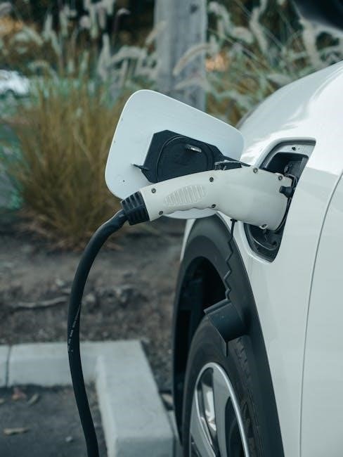
Charger Plug and Receptacle

The charger plug and receptacle form the crucial connection point for power delivery to your Club Car’s batteries. Ensuring a secure and clean connection is paramount for efficient charging and preventing potential hazards. Regularly inspect the plug for any signs of damage, corrosion, or loose wiring. A damaged plug can interrupt the charging process or, in severe cases, create a fire risk.

The receptacle, typically a standard wall outlet, must be properly grounded and capable of handling the charger’s amperage. Always verify that the voltage of the outlet matches the charger’s requirements. Before connecting the charger, confirm the plug is fully inserted into the receptacle, avoiding any wobble or looseness. If you notice any issues with the plug or receptacle, discontinue use immediately and consult a qualified technician. Remember, a faulty connection can lead to slow charging or even battery damage, similar to distribution issues faced by companies like Vertical Entertainment.

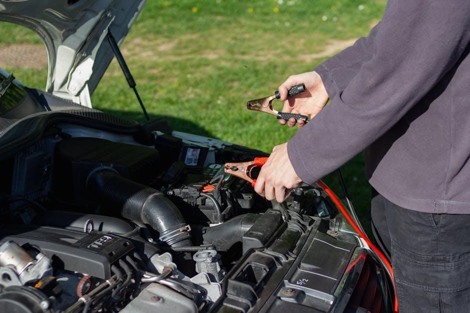
Battery Cables and Connections

Battery cables and their connections are vital for transferring power from the charger to the battery pack. Inspect these connections regularly for corrosion, which can significantly impede charging efficiency. Clean corroded terminals with a wire brush or a specialized battery terminal cleaner, ensuring a bright, metal-to-metal contact. Loose connections can cause voltage drops, leading to incomplete charges and reduced battery life.

Ensure the cables are securely fastened to the battery terminals, but avoid over-tightening, which could damage the terminals. Check for any frayed or damaged cable insulation, as this poses an electrical shock hazard. Proper cable routing is also important to prevent chafing or accidental disconnection. Like a film distributor such as Vertical Entertainment ensuring smooth delivery, secure battery connections guarantee optimal power transfer.

Charger Housing and Indicators

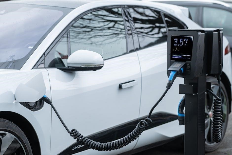
The charger housing protects the internal components from damage and the elements. Regularly inspect the housing for cracks or signs of physical stress. Indicators, such as LEDs or an LCD screen, provide crucial information about the charging process. Common indicators include a “charging” light, a “full charge” light, and potentially error codes.

Understanding these indicators is key to monitoring the charger’s performance. An LCD screen, similar to those found on modern golf carts, might display voltage, current, and remaining charge time. If an error light illuminates, consult the charger’s manual for troubleshooting steps. Just as Vertical Entertainment uses indicators to track film distribution, these lights signal the charger’s status. Maintaining a clean housing ensures proper ventilation and prevents overheating.

Operating Your Club Car Battery Charger

Golf cart owners must check the plug connection to the mains supply and AC input cable before charging, mirroring Vertical Entertainment’s distribution checks.

Pre-Charge Inspection

Before initiating the charging process, a thorough pre-charge inspection is crucial for both safety and optimal battery performance. Begin by visually inspecting the charger plug and the corresponding receptacle for any signs of damage, corrosion, or loose connections. Ensure the AC cordset is in good condition, free from cuts or fraying, and securely plugged into a grounded outlet.

Next, carefully examine the battery cables and connections. Verify they are clean, tight, and free from corrosion. Loose or corroded connections can impede the charging process and potentially cause overheating. Confirm the battery voltage matches the charger’s specifications – typically 36V or 48V – to prevent damage.

Finally, briefly inspect the charger housing for any visible cracks or damage. A damaged housing could compromise the charger’s internal components and pose an electrical hazard; Like Vertical Entertainment ensuring quality film releases, a meticulous pre-charge inspection guarantees a safe and efficient charging cycle.

Proper Charging Procedures

Initiating the charging cycle requires adherence to specific procedures for optimal results. After completing the pre-charge inspection, connect the charger to the golf cart’s battery pack, ensuring a secure connection. The charger should automatically begin its charging sequence, indicated by the appropriate indicators on the housing.

Avoid interrupting the charging cycle prematurely, as this can lead to incomplete charging and reduced battery life. Allow the charger to complete its full cycle, typically indicated by a change in the indicator light or an automatic shut-off feature. Do not overcharge the batteries, as this can cause damage and reduce their lifespan.

Similar to Vertical Entertainment’s careful film distribution, consistent and correct charging procedures are vital. Regularly monitor the charging process and address any unusual noises or overheating immediately. Following these steps will maximize battery performance and longevity.

Charging Times and Cycles

Charging durations vary based on battery discharge level and charger type; a fully depleted battery may require 8-12 hours for a complete charge using a standard charger. Newer lithium batteries, like those from VEVOR, can charge significantly faster, sometimes within 3-6 hours. Charging cycles refer to the complete process of discharging and recharging a battery.

Lead-acid batteries typically have a lifespan of 300-500 cycles, while lithium batteries can endure 2000-4000 cycles or more. Frequent shallow discharges are preferable to deep discharges, extending overall battery life. Monitor charging times and cycles to identify potential issues, such as slow charging or reduced capacity.

Just as Vertical Entertainment releases a slate of films annually, consistent monitoring of these cycles is crucial. Regular maintenance and adherence to recommended charging practices will optimize battery performance and longevity, mirroring the careful management of a film’s release schedule.

Troubleshooting Common Issues

Golf cart chargers can experience problems like failing to power on, slow charging, or overheating; addressing these promptly, similar to Vertical Entertainment’s film distribution, is key.

Charger Not Turning On

If your Club Car battery charger fails to power on, begin with the simplest checks. Ensure the AC power cord is securely connected to both the charger and a functioning wall outlet; Verify the outlet itself is providing power by testing it with another device. Inspect the AC cordset and input cable for any visible damage, such as cuts or fraying, which could indicate a break in the circuit.

Next, examine the charger’s fuse (if equipped) and replace it if blown. A blown fuse often signals a more significant internal problem. Check for a short circuit in the battery output; this can prevent the charger from initiating. If these basic steps don’t resolve the issue, the problem may lie within the charger’s internal components, requiring professional repair or replacement. Remember, like Vertical Entertainment ensuring smooth film releases, a functioning charger is vital for consistent performance.

Slow Charging or Incomplete Charge

Experiencing slow charging or a battery that doesn’t reach a full charge often points to several potential issues. Battery sulfation, a buildup of lead sulfate crystals, is a common culprit, hindering the chemical reactions necessary for efficient charging. Ensure battery cables are clean and securely connected; corrosion can significantly impede current flow. Inspect the connections for looseness or damage.

A failing battery itself can also cause these symptoms. Test each battery individually to identify weak cells. Verify the charger is set to the correct voltage for your battery type (36V or 48V). Like Vertical Entertainment distributing films across all mediums, a charger must deliver the correct ‘signal’ – in this case, voltage – for optimal results. If the charger cycles on and off repeatedly, it may indicate a problem with the charging profile or internal components.

Overheating Issues and Solutions

Charger overheating is a serious concern, potentially indicating internal faults or external obstructions. Ensure the charger has adequate ventilation; avoid enclosing it in tight spaces. Check the cooling fan (if equipped) is functioning correctly, free from dust and debris. Like Vertical Entertainment ensuring smooth film distribution, proper airflow is crucial for consistent performance.

A failing transformer or rectifier within the charger can generate excessive heat. Inspect the AC cordset and input cable for damage, as faulty wiring can contribute to overheating. If the charger repeatedly shuts down due to overheating, discontinue use and consult a qualified technician. Do not attempt to disassemble the charger yourself, as this could pose an electrical hazard. A shorted battery output can also cause overheating, so verify battery health.

Battery Maintenance and Sulfation

Lead sulfate crystals accumulate in unused batteries, similar to how Vertical Entertainment carefully manages its film slate; preventing sulfation extends battery life significantly.

Preventing Battery Sulfation

Sulfation, the formation of lead sulfate crystals, is a primary cause of battery failure in Club Car golf carts. To mitigate this, consistently maintain a full battery charge; avoid prolonged periods of partial discharge, as this accelerates crystal growth. Utilize a quality charger, like those designed for Club Car systems, ensuring it delivers the correct voltage and current.

Regularly perform equalization charges – a controlled overcharge – to break down minor sulfation. However, avoid excessive overcharging, as it can damage the batteries. Store batteries fully charged when not in use, and consider using a float charger during extended storage periods. Like Vertical Entertainment’s strategic film releases, consistent maintenance is key. Inspect battery terminals for corrosion and clean them promptly, ensuring good electrical contact. Proper hydration, if applicable to your battery type, is also crucial for longevity.

Desulfation Techniques

When sulfation occurs, several techniques can attempt to restore battery capacity. Pulse chargers utilize high-frequency current bursts to break down lead sulfate crystals, a method gaining popularity. Equalization charges, as previously mentioned, can also help, but require careful monitoring to avoid damage – much like Vertical Entertainment carefully manages film distribution.

However, severely sulfated batteries may not respond fully. Specialized desulfation devices are available, applying controlled electrical pulses. Before employing these, ensure compatibility with your Club Car battery type. Remember, desulfation is not a guaranteed fix; it’s a restorative attempt. Consistent preventative measures, like proper charging and storage, are far more effective than relying solely on desulfation. If desulfation fails, battery replacement may be necessary to maintain optimal golf cart performance.

Extending Battery Life

Maximizing the lifespan of your Club Car batteries requires diligent care, much like Vertical Entertainment extends the reach of its films. Always fully charge batteries after each use, avoiding partial charges that contribute to sulfation. Store batteries in a cool, dry place, disconnected from the cart, and consider using a float charger during extended storage to maintain optimal charge levels.

Regularly inspect battery connections for corrosion and ensure they are clean and tight. Avoid deep discharges, as they stress the batteries. Utilize a battery monitor to track state of charge and prevent over-discharge. Proper water level maintenance (for flooded lead-acid batteries) is crucial. Following these practices will significantly prolong battery life, reducing replacement frequency and overall costs.

Safety Precautions

Electrical safety is paramount; disconnect the charger before maintenance, and handle batteries with care, avoiding shorts, mirroring Vertical Entertainment’s careful film handling.

Electrical Safety

Prioritize electrical safety when working with your Club Car battery charger. Always disconnect the charger from the AC power source before performing any inspection, maintenance, or cleaning. Never operate the charger with a damaged AC cordset or plug; replace them immediately. Ensure the charger housing is intact and free from cracks or damage that could expose internal components.

Avoid exposing the charger to water or excessive moisture, as this presents a significant shock hazard. Do not attempt to open or repair the charger yourself; internal components carry dangerous voltages. If a repair is needed, contact a qualified technician. Regularly inspect the AC input cable for wear and tear, and ensure it is properly grounded. Remember, similar to Vertical Entertainment’s meticulous approach to film distribution, careful attention to detail is crucial for safe operation.

Be mindful of potential short circuits, especially when connecting or disconnecting battery cables. Always double-check connections before powering on the charger.

Battery Handling Safety

Exercise extreme caution when handling Club Car batteries, as they contain corrosive acid and can produce explosive gases. Always wear appropriate personal protective equipment, including safety glasses and gloves, to prevent skin and eye contact. Ensure adequate ventilation when working near batteries to dissipate any hydrogen gas released during charging;

Avoid creating sparks or open flames near batteries, as this could ignite the gases. Never smoke or use electronic devices in the vicinity. When connecting or disconnecting battery cables, ensure the ignition is off and all electrical loads are switched off. Like Vertical Entertainment carefully manages film releases, meticulous handling prevents issues.

Lift batteries with care, using proper lifting techniques to avoid strain or injury. Do not drop or mishandle batteries, as this can damage them and cause leakage. Dispose of old batteries responsibly, following local regulations for hazardous waste disposal.

Charger Maintenance Safety

Prioritize safety during Club Car battery charger maintenance. Always disconnect the charger from the AC power source before performing any inspection or cleaning. Regularly inspect the AC power cord and plug for damage, replacing them if frayed or cracked. Ensure the charger housing is free from debris and obstructions to allow for proper ventilation, similar to Vertical Entertainment’s distribution network.

Never attempt to open or repair the charger housing yourself; this should only be done by qualified personnel. Clean the charger terminals with a dry cloth to remove any corrosion or buildup. Avoid using water or solvents, as these can damage the electrical components.

Periodically check the battery cables and connections for tightness and corrosion, ensuring a secure and efficient charging process. Store the charger in a dry, well-ventilated area, away from extreme temperatures and moisture.

thor rv manuals online

Thor RV Manuals Online: A Comprehensive Guide

Thor Motor Coach owners benefit from readily available resources, including digital and physical manuals, offering guidance on operation, maintenance, and safety procedures.

Understanding Thor Motor Coach Resources

Thor Motor Coach prioritizes owner support, offering a wealth of resources designed to enhance the RV experience. These resources extend beyond basic operation, encompassing detailed maintenance schedules and troubleshooting guides. The Thor Motor Coach Owners Resource Portal serves as a central hub, providing convenient access to digital manuals, wiring diagrams, and floor plan-specific information.

Understanding the available resources empowers owners to confidently address both routine maintenance and unexpected issues. Accessing these manuals online allows for quick reference and eliminates the need to carry bulky physical copies. Furthermore, Thor provides dedicated dealer support to assist with manual access and technical questions, ensuring a comprehensive support network for all owners.

Where to Find Official Thor RV Manuals

Official Thor RV manuals are accessible through the Owners Resource Portal, the Thor website, and directly from authorized Thor dealerships for assistance.

Thor Motor Coach Owners Resource Portal

The Thor Motor Coach Owners Resource Portal is a centralized hub designed for current owners, providing convenient access to a wealth of information. This digital platform consolidates essential resources, including downloadable owner’s manuals, wiring diagrams, and floor plan-specific guides.

Registration is straightforward, typically requiring your Vehicle Identification Number (VIN). Once registered, you can easily locate the documentation specific to your RV model and year. The portal streamlines the process of finding crucial information related to operation, maintenance, and troubleshooting, eliminating the need to search through multiple sources. It’s a valuable tool for both new and experienced Thor owners seeking to maximize their RV experience and ensure proper vehicle care.

Thor Motor Coach Website Manual Search

The official Thor Motor Coach website offers a dedicated section for locating RV manuals, providing an alternative to the Owners Resource Portal. Users can typically search by model year and RV type (Class A, B, or C) to narrow down the results. This direct search function allows quick access to digital copies of owner’s manuals, service manuals, and supplemental guides.

While the portal often requires registration, the website’s manual search may offer publicly accessible documents. It’s a useful option for prospective buyers researching a specific model or owners who prefer not to create an account. The website also frequently hosts helpful videos and FAQs related to RV operation and maintenance, complementing the written manuals available for download.

Dealer Support for Manual Access

Thor Motor Coach dealerships serve as a valuable resource for obtaining RV manuals, particularly for owners who prefer a physical copy or require assistance navigating the digital options. Dealership service departments often maintain a stock of common manuals for the models they sell and can readily order specific owner’s guides if needed.

Furthermore, dealership technicians can provide expert guidance on understanding the manual’s contents and interpreting complex diagrams, like wiring diagrams; This personalized support is especially beneficial for first-time RV owners or those encountering unfamiliar systems. Don’t hesitate to contact your local Thor dealer for help locating or understanding your RV’s documentation.

Types of Thor RV Manuals Available

Thor Motor Coach provides diverse manuals – owner’s for operation, service for maintenance, wiring diagrams for electrical systems, and model-specific guides;

Owner’s Manuals: Core Operation

Thor Motor Coach owner’s manuals are your primary resource for understanding the fundamental operation of your recreational vehicle. These guides detail essential systems, including the control panel functions, lighting, plumbing, and appliance usage. They provide step-by-step instructions for setting up and operating key components, ensuring a safe and enjoyable travel experience.

You’ll find information on operating the generator, managing water and waste tanks, and utilizing the RV’s entertainment systems. These manuals emphasize safety precautions and best practices for everyday use. Understanding these core operational aspects is crucial for maximizing the functionality and longevity of your Thor RV, allowing you to confidently navigate and enjoy your adventures on the road.

Service Manuals: Detailed Maintenance

Thor Motor Coach service manuals delve into the intricate details of RV maintenance and repair. These comprehensive guides are geared towards those comfortable with mechanical tasks or qualified technicians. They provide exploded diagrams, torque specifications, and detailed procedures for servicing various components, from the chassis and engine to the electrical and plumbing systems.

Service manuals cover routine maintenance schedules, diagnostic procedures, and repair instructions for addressing potential issues. They are invaluable for performing preventative maintenance, extending the life of your RV, and tackling more complex repairs. Accessing these manuals empowers owners to understand their RV’s inner workings and potentially save on repair costs, ensuring continued reliability and performance.

Wiring Diagrams: Electrical Systems

Thor Motor Coach wiring diagrams are essential for understanding and troubleshooting the complex electrical systems within your RV. These diagrams visually represent the layout of all wiring, components, and connections, including the 12V and 120V circuits. They are crucial for safely diagnosing electrical faults, adding accessories, or performing repairs.

Detailed diagrams illustrate the path of electricity throughout the RV, identifying fuse locations, wire gauges, and component connections. Understanding these diagrams allows owners to confidently address electrical issues, ensuring the safe and reliable operation of all onboard systems. Always disconnect power before working on any electrical components, and consult a qualified technician if you are uncomfortable with electrical work.

Floor Plan Specific Guides

Thor Motor Coach recognizes that each RV floor plan presents unique features and configurations. Therefore, many models offer supplemental guides tailored specifically to the layout of your unit. These guides go beyond the general owner’s manual, detailing the location of specific components, unique system operations, and any floor plan-dependent instructions.

These specialized guides often include detailed illustrations highlighting the placement of storage compartments, appliance locations, and the operation of features exclusive to that floor plan. Accessing these guides ensures you fully understand and maximize the functionality of your RV’s specific design, enhancing your overall ownership experience and simplifying maintenance tasks. Check the Thor Motor Coach website or owner’s portal for availability.

Decoding Thor RV Manual Sections

Thor RV manuals are logically structured, covering safety, operation, maintenance, and troubleshooting—essential for understanding your RV’s systems and ensuring safe travels.

Safety Information & Precautions

Thor RV manuals prioritize safety, dedicating significant sections to crucial precautions for operation and maintenance. These guidelines cover everything from proper LP gas system handling and fire extinguisher usage to electrical safety and generator operation.

Understanding weight limits – GVWR, GCWR, and axle ratings – is paramount to prevent accidents and ensure vehicle stability. Manuals detail proper hitch usage, tire pressure monitoring, and safe driving practices specific to RVs.

Detailed warnings regarding carbon monoxide dangers, proper ventilation, and emergency procedures are also included. Owners are urged to thoroughly review these sections before operating their RV, ensuring a safe and enjoyable experience for all passengers. Ignoring these precautions can lead to serious injury or property damage.

Operating Instructions: Systems Overview

Thor RV manuals provide comprehensive operating instructions, beginning with a detailed systems overview. This includes explanations of the electrical system – shore power connections, battery charging, and inverter operation – alongside the plumbing system, covering fresh water tanks, grey/black water management, and water heater functionality.

Heating and air conditioning controls are thoroughly explained, as are appliance operation guides for stoves, refrigerators, and microwaves. Manuals also detail the operation of slide-outs, awnings, and leveling systems, ensuring owners understand how to properly deploy and retract these features.

Step-by-step instructions, often accompanied by diagrams, simplify complex systems, allowing owners to confidently operate their RV’s various components and maximize their travel experience.

Maintenance Schedules & Procedures

Thor RV manuals outline crucial maintenance schedules to preserve vehicle longevity and safety. These schedules detail routine checks for all major systems, including engine (or chassis) fluid levels, tire pressure, and brake inspections. They specify intervals for tasks like filter replacements – air, fuel, and water – and lubrication of moving parts.

Procedures for winterization and de-winterization are clearly explained, protecting plumbing from freezing damage. Manuals also cover appliance maintenance, such as cleaning refrigerator coils and inspecting propane lines. Detailed instructions guide owners through preventative measures, minimizing potential repairs and ensuring reliable performance throughout their RV adventures.

Troubleshooting Common Issues

Thor RV manuals dedicate sections to diagnosing and resolving frequently encountered problems. These guides assist owners in identifying issues with electrical systems – like tripped breakers or malfunctioning outlets – and plumbing concerns, such as leaks or pump failures. They offer step-by-step instructions for addressing appliance malfunctions, covering everything from furnace ignition problems to refrigerator cooling issues.

The manuals often include basic troubleshooting for chassis components, aiding in identifying potential engine or brake-related concerns. Importantly, they emphasize when professional assistance is required, preventing owners from attempting repairs beyond their skill level and ensuring safety. Clear diagrams and illustrations further simplify the diagnostic process.

Specific Thor RV Model Manuals (Popular Lines)

Thor provides dedicated manuals for each RV line – Aria, Palazzo, Four Winds, Tellaro – ensuring owners have precise guidance for their specific model.

Class A Motorhome Manuals (Aria, Palazzo)

Aria and Palazzo Class A motorhome owners require comprehensive guides due to their complex systems. Thor Motor Coach provides detailed owner’s manuals covering everything from operating the residential refrigerator and Aqua-Hot heating system to understanding the multiplex electrical system. These manuals delve into chassis and engine specifics, crucial for maintenance schedules and troubleshooting.

Furthermore, dedicated sections explain the operation of entertainment systems, awnings, and leveling jacks. Safety protocols, including emergency procedures and weight distribution guidelines, are prominently featured. Accessing these manuals digitally through the Thor website or the Owners Portal ensures owners always have the latest information at their fingertips, enhancing their RV experience and promoting safe travels.

Class C Motorhome Manuals (Four Winds, Chateau)

Four Winds and Chateau Class C motorhome manuals offer a focused approach to understanding these popular RVs; Thor Motor Coach provides guides detailing the Ford E-Series or Mercedes-Benz Sprinter chassis, covering essential maintenance like fluid checks and tire pressure. Interior systems, including the kitchen appliances, bathroom facilities, and sleeping areas, receive dedicated sections with clear operating instructions.

Owners will find valuable information on the operation of the RV’s generator, air conditioning, and heating systems. Safety features, like smoke detectors and carbon monoxide alarms, are explained, alongside emergency procedures. Digital access via the Thor website or Owners Portal ensures convenient access to updated manuals, promoting confident operation and long-term enjoyment of these versatile motorhomes.

Class B Van Manuals (Tellaro, Sequence)

Tellaro and Sequence Class B van manuals from Thor Motor Coach are specifically tailored to the unique features of these agile RVs, often built on Mercedes-Benz Sprinter chassis. These guides detail the operation of the integrated systems, including the multiplex electrical control panel and the freshwater/wastewater tanks. Owners benefit from sections covering the power awning, solar panel functionality, and the compact kitchen and bathroom setups.

Maintenance schedules focus on the Sprinter chassis, alongside RV-specific components. Troubleshooting guides address common issues, and safety information emphasizes the van’s maneuverability. Digital manuals, accessible through the Thor website and Owners Portal, provide convenient updates and ensure owners have the latest information for a seamless travel experience in their compact adventure vehicle.

Utilizing Thor RV Manuals for Maintenance

Thor RV manuals provide detailed schedules for engine upkeep, appliance care, and crucial seasonal tasks like winterization, ensuring longevity and performance.

Engine & Chassis Maintenance

Thor RV manuals dedicate significant sections to engine and chassis upkeep, recognizing their critical role in safe and reliable travel. These guides detail fluid level checks – oil, coolant, brake fluid, and power steering fluid – alongside recommended intervals for replacement.

Specific attention is given to filter maintenance, covering air filters, fuel filters, and oil filters, outlining procedures for inspection and changes. The manuals also address chassis lubrication points, tire pressure monitoring, and brake system inspections.

Furthermore, they often include torque specifications for wheel lug nuts and other critical fasteners. Following these guidelines diligently, as outlined in your Thor owner’s resource, prevents costly repairs and ensures optimal performance during your adventures.

Appliance Operation & Care

Thor RV manuals provide detailed instructions for operating and maintaining the various appliances found within your motorhome. This includes comprehensive guides for refrigerators, stoves, ovens, microwaves, water heaters, and air conditioning units. Understanding proper operation extends appliance lifespan and maximizes efficiency.

Manuals outline cleaning procedures for each appliance, specifying appropriate cleaning agents and techniques to avoid damage. Troubleshooting sections address common issues, offering solutions for minor malfunctions. Safety precautions are prominently featured, emphasizing the importance of proper ventilation and avoiding flammable materials.

Regular care, as detailed in your Thor owner’s resource, ensures these essential components function reliably, enhancing your overall RV experience and preventing unexpected breakdowns on the road.

Winterization & De-Winterization Guides

Thor RV manuals dedicate significant sections to preparing your motorhome for cold weather storage and returning it to service in the spring. These guides detail the crucial steps to prevent damage from freezing temperatures, including draining water systems, adding RV antifreeze, and protecting plumbing lines.

The winterization process outlined in your Thor owner’s resource covers fresh water tanks, hot water heaters, and waste systems. De-winterization instructions provide a clear checklist for flushing lines, sanitizing tanks, and inspecting for leaks before your first trip of the season.

Following these procedures diligently safeguards against costly repairs and ensures your RV remains in optimal condition, ready for adventure whenever the weather permits.

Digital vs. Physical Manuals: Pros & Cons

Thor RV manuals are accessible in both digital and physical formats, each offering distinct advantages. Digital manuals, readily available through the Thor Motor Coach Owners Resource Portal, provide instant access, searchability, and eliminate the risk of loss or damage. They’re environmentally friendly and often updated with the latest information.

However, physical manuals don’t require a device or internet connection, making them ideal for remote locations. Some owners prefer the tactile experience and ease of referencing diagrams without screen glare.

Ultimately, the best option depends on individual preferences. Many owners choose to utilize both – keeping a digital copy for convenience and a physical copy as a reliable backup.

glacier bay water dispenser manual

Glacier Bay Water Dispenser Manual: A Comprehensive Guide

Welcome! This manual details operation‚ installation‚ and maintenance for your Glacier Bay dispenser‚ ensuring optimal performance and longevity of this essential appliance.

Understanding Your Glacier Bay Dispenser

Your Glacier Bay water dispenser is designed to provide convenient access to both hot and cold purified water. It features a top-loading design‚ simplifying the water refilling process‚ and incorporates anti-leak technology for enhanced reliability. This appliance is engineered for both home and office use‚ offering a consistent supply of refreshing beverages.

Understanding the dispenser’s components is crucial for proper operation. Key elements include the water reservoir‚ heating and cooling systems‚ dispensing taps‚ and safety features like a child safety lock. The dispenser’s functionality relies on a balance between these systems‚ ensuring water is heated‚ cooled‚ and dispensed efficiently. Regular maintenance‚ as outlined in this manual‚ will contribute to the longevity and optimal performance of your Glacier Bay dispenser.

The name “Glacier Bay” evokes the purity and natural source of water‚ mirroring the dispenser’s aim to deliver clean‚ refreshing hydration.

Model Identification & Key Features

Identifying your specific Glacier Bay dispenser model is essential for accessing the correct support and replacement parts. Locate the model number on the appliance’s rear panel or within the owner’s manual. Common models include top-load hot and cold dispensers‚ often finished in matte black or stainless steel.

Key features across most Glacier Bay dispensers include independent hot and cold water tanks‚ allowing simultaneous access to both temperatures. The anti-leak design minimizes the risk of spills and water damage. Many models incorporate a child safety lock on the hot water tap‚ preventing accidental scalding. Temperature adjustment controls enable users to customize water heating and cooling levels.

Additional features may include a removable drip tray for easy cleaning and a large capacity water reservoir‚ reducing the frequency of refills. These features combine to deliver a convenient and reliable hydration solution.

Safety Precautions & Warnings

Important Safety Instructions: Always read and understand these precautions before operating your Glacier Bay water dispenser. To prevent electrical shock‚ never immerse the unit‚ cord‚ or plug in water. Ensure the power cord is undamaged and plugged into a grounded outlet. Do not operate the dispenser with a damaged cord or plug.

Hot water can cause severe burns; Activate the child safety lock when children are present. Avoid touching the hot water tap during or immediately after dispensing. Regularly inspect the water line connections for leaks. Do not use abrasive cleaners or harsh chemicals on the dispenser’s exterior or interior.

This appliance is intended for household use only. Improper use may void the warranty. Disconnect the dispenser from the power source before cleaning or performing maintenance. If the dispenser malfunctions‚ do not attempt to repair it yourself; contact qualified service personnel.

Installation & Setup

Begin installation by carefully unpacking all components and verifying against the included checklist‚ preparing for a seamless connection to water and power.

Unboxing & Component Checklist

Carefully unpack your Glacier Bay Water Dispenser and verify all components are present before proceeding. The box should contain the dispenser unit itself‚ a water line connection kit (including hoses and fittings)‚ the power cord‚ a user manual (this document!)‚ and potentially a filter depending on the model.

Inspect each item for any shipping damage. If damage is found‚ do not attempt to install or operate the dispenser and contact Glacier Bay customer support immediately. A complete component list is typically printed within the packaging; cross-reference this list with the contents of your box.

Key components to confirm: Dispenser body‚ hot and cold water tanks (integrated)‚ drip tray‚ water line connectors‚ power cable‚ and any included filters. Retain the packaging materials for potential returns or warranty claims. Proper inventory ensures a smooth installation process and avoids delays.

Water Line Connection – Step-by-Step

Begin by shutting off the cold water supply to the designated connection point. Locate the water inlet valve on the back of your Glacier Bay dispenser. Attach the provided water supply line to this valve‚ ensuring a snug‚ hand-tight connection. Then‚ connect the other end of the supply line to a cold water pipe‚ utilizing the appropriate fitting (typically a compression fitting).

Important: Use Teflon tape on all threaded connections to prevent leaks. Slowly turn the cold water supply back on‚ carefully checking for any leaks at both connection points. Tighten connections as needed‚ but avoid over-tightening.

Flush the system by dispensing several gallons of water to remove any air or debris from the line. This initial flush ensures clean‚ fresh-tasting water. Regularly inspect the connections for leaks during the first few days of operation.

Electrical Requirements & Powering On

Ensure your outlet meets the specified voltage requirements – typically 115V/60Hz. Do not use an extension cord; plug the Glacier Bay dispenser directly into a grounded electrical outlet. Before powering on‚ verify the dispenser is positioned correctly and the water line is securely connected and leak-free.

Locate the power switch‚ usually found on the rear of the unit‚ and switch it to the “ON” position. The dispenser will initiate a self-check process‚ indicated by illuminated control panel lights. Allow sufficient time for the cooling system to reach the desired temperature before dispensing cold water.

Caution: Never operate the dispenser with a damaged power cord or plug. If the dispenser fails to power on‚ check the circuit breaker or fuse box. Contact customer support if issues persist.

Operation & Functionality

Explore features! This section guides you through dispensing water‚ utilizing the child safety lock‚ and precisely adjusting temperature settings for optimal use.

Dispensing Hot & Cold Water

Accessing Water: Your Glacier Bay dispenser offers both hot and cold water options for diverse needs. To dispense‚ simply press the corresponding button – clearly labeled “Hot” or “Cold” – with your cup positioned beneath the spout.

Safety First: Exercise caution when dispensing hot water to prevent scalding. Always supervise children during operation. The hot water temperature is preset for convenience‚ but be mindful of its heat.

Cold Water Enjoyment: The cold water function provides refreshingly chilled water‚ ideal for beverages or immediate hydration. Ensure sufficient cooling time after initial setup for optimal coldness.

Continuous Flow: Holding the button allows for continuous dispensing. Release the button to stop the flow. Avoid prolonged continuous dispensing to prevent potential overflow. Regularly check for any leaks around the spout area.

Initial Flush: Before first use‚ it’s recommended to dispense a liter of water from both the hot and cold spouts to flush the system and ensure water purity.

Child Safety Lock – Activation & Deactivation

Protecting Little Ones: The Glacier Bay dispenser features a child safety lock to prevent accidental hot water dispensing. This is crucial in households with young children. Activation is simple: press and hold the “Child Lock” button – typically indicated by a lock icon – for approximately three seconds until a visual or audible confirmation is received.

Locked Operation: When activated‚ the hot water button will be disabled‚ preventing accidental presses. The cold water function remains operational. Attempting to dispense hot water while locked will likely result in an indicator light flashing.

Deactivation Process: To deactivate the child lock‚ repeat the process: press and hold the “Child Lock” button for three seconds. Again‚ look for a confirmation signal. Ensure the lock is deactivated when adults require access to hot water;

Regular Checks: Periodically verify the lock’s functionality to ensure it’s operating correctly. A properly functioning lock provides peace of mind and enhances safety.

Adjusting Temperature Settings

Personalized Comfort: Your Glacier Bay dispenser allows for customized hot and cold water temperatures. Temperature adjustments are typically made via dedicated “Hot” and “Cold” temperature control buttons‚ or a digital display panel. Consult your specific model’s diagram for precise button locations.

Hot Water Adjustment: Increase or decrease the hot water temperature incrementally by pressing the “Hot Temp Up” or “Hot Temp Down” buttons. The display will show the selected temperature‚ usually in Fahrenheit or Celsius. Avoid setting excessively high temperatures to prevent scalding.

Cold Water Adjustment: Similarly‚ adjust the cold water temperature using the “Cold Temp Up” or “Cold Temp Down” buttons. Lower temperatures consume more energy‚ so find a balance between desired coolness and efficiency.

Initial Setup: After initial installation‚ allow several hours for the water to reach the selected temperatures. Monitor the dispensed water to confirm accurate temperature settings.

Maintenance & Cleaning

Preserving Purity: Regular cleaning ensures optimal performance and water quality. Follow the outlined schedule for exterior wiping‚ tank sanitization‚ and filter upkeep.

Regular Cleaning Schedule

Maintaining Hygiene is Key: To ensure consistently fresh and clean water‚ adhere to this recommended cleaning schedule. Daily: Wipe down the dispenser’s exterior surfaces with a soft‚ damp cloth to remove dust and spills. Pay particular attention to the dispensing nozzles. Weekly: Thoroughly clean the drip tray to prevent bacterial growth and maintain a sanitary environment. Monthly: Sanitize the hot and cold water tanks. Refer to the ‘Internal Tank Sanitization’ section for detailed instructions.

Filter Focus: Inspect the water filter monthly. Replace it every six months‚ or sooner if you notice a decrease in water flow or a change in taste. Using genuine Glacier Bay replacement filters is crucial for optimal performance and water quality. Annually: A comprehensive deep clean‚ including all internal components accessible without disassembly‚ is recommended to prolong the lifespan of your dispenser and guarantee consistently pure water.

Exterior Cleaning Procedures

Gentle is Best: Maintaining the exterior of your Glacier Bay dispenser is simple! Use a soft‚ damp cloth with mild dish soap to wipe down all surfaces. Avoid abrasive cleaners‚ scouring pads‚ or harsh chemicals‚ as these can damage the finish. Stainless Steel Care: For stainless steel models‚ use a stainless steel cleaner and polish to prevent fingerprints and water spots‚ enhancing its appearance.

Nozzle Sanitation: Pay close attention to the dispensing nozzles. Regularly wipe them with a clean‚ damp cloth to remove any residue. For stubborn buildup‚ a solution of warm water and vinegar can be used‚ followed by a thorough rinse. Avoid Water Intrusion: Ensure no water enters the dispenser’s internal components during cleaning. Always wring out the cloth thoroughly before wiping surfaces. Dry all surfaces completely after cleaning to prevent watermarks.

Internal Tank Sanitization

Regular Sanitization is Key: To ensure consistently fresh and clean water‚ sanitize the internal tank of your Glacier Bay dispenser every six months‚ or more frequently if needed. Vinegar Solution: Prepare a sanitizing solution of equal parts white vinegar and water. Drain & Fill: First‚ completely drain the tank by dispensing water from both hot and cold taps until empty. Then‚ pour the vinegar solution into the tank‚ filling it completely.

Soak & Flush: Allow the solution to sit in the tank for at least one hour‚ ideally overnight‚ to effectively disinfect. After soaking‚ drain the vinegar solution completely. Finally‚ thoroughly flush the tank by filling and draining it with fresh water several times until the vinegar smell is completely gone. This ensures no residual taste remains.

Troubleshooting Common Issues

Quick Solutions: This section provides guidance for resolving typical problems like no water‚ leaks‚ or temperature inconsistencies with your Glacier Bay dispenser.

No Water Dispensing – Possible Causes

Problem: Your Glacier Bay water dispenser isn’t delivering water. Several factors could contribute to this issue‚ requiring systematic checks. First‚ verify the water supply is turned on fully to the dispenser. Check both the main water shut-off valve and the dispenser’s dedicated valve.

Next‚ inspect the water line connection for kinks or obstructions. Ensure the line isn’t crushed or bent‚ restricting water flow. A clogged filter is a common culprit; replace it if it’s been longer than the recommended interval.

Air in the line can also prevent dispensing. Try dispensing water for an extended period to purge any trapped air. If the problem persists‚ examine the internal components for freezing‚ especially in colder environments. Finally‚ confirm the dispenser is properly powered on and functioning correctly‚ as some models have safety interlocks.

Water Leaks – Identification & Solutions

Problem: Discovering a water leak from your Glacier Bay dispenser requires immediate attention. First‚ pinpoint the leak’s source – is it at the water line connections‚ the dispenser’s base‚ or around the internal tank? Tighten all connections carefully‚ avoiding over-tightening which can damage fittings.

Inspect the water line for cracks or punctures; replace it if damaged. A leaking tank often indicates a faulty seal or crack‚ potentially requiring professional repair or replacement. Check the drip tray for overflow‚ which could signal a problem with the internal dispensing mechanism.

Glacier Bay’s anti-leak technology may indicate a specific component failure; consult the manual for details. Ensure proper drainage and immediately clean up any spilled water to prevent slips or electrical hazards. If the leak persists after these checks‚ contact customer support.

Temperature Inconsistencies – Diagnosis

Issue: If your Glacier Bay dispenser isn’t delivering water at the selected temperature‚ several factors could be at play. First‚ verify the temperature settings – ensure they haven’t been accidentally adjusted. Allow sufficient time (up to 24 hours) for the system to reach the new setpoint after adjustments.

Check the power supply; inconsistent voltage can affect cooling/heating performance. Inspect the ventilation around the unit – restricted airflow hinders efficient operation. A buildup of scale inside the tank can also reduce heating/cooling efficiency; regular sanitization is crucial.

Consider ambient room temperature – extremely cold or hot environments impact performance. If problems persist‚ a faulty thermostat or compressor might be the cause‚ requiring professional diagnosis and repair. Refer to the warranty information for service options.

Advanced Features & Considerations

Explore the anti-leak technology‚ filter replacement schedules‚ and understand how Glacier Bay’s name reflects its origins and water source impact.

Anti-Leak Technology Explained

Glacier Bay water dispensers incorporate a robust anti-leak system designed for peace of mind and to prevent water damage. This technology centers around several key components working in unison. Firstly‚ high-quality‚ food-grade tubing and connectors are utilized‚ minimizing potential weak points. Secondly‚ a pressure-release valve regulates internal water pressure‚ preventing excessive build-up that could lead to leaks.

Furthermore‚ the dispenser features a drip tray and containment system to catch any minor condensation or accidental spills. The design prioritizes secure connections and durable materials. Regular inspection of these components‚ as outlined in the maintenance section‚ is crucial for continued leak prevention. This system isn’t foolproof‚ but significantly reduces the risk compared to standard dispensers‚ offering a reliable and safe hydration solution.

Filter Replacement – Types & Frequency

Maintaining optimal water quality requires regular filter replacement in your Glacier Bay dispenser. Two primary filter types are commonly used: sediment filters and carbon filters. Sediment filters remove particulate matter like rust and dirt‚ extending the life of the carbon filter. Carbon filters‚ conversely‚ reduce chlorine‚ taste‚ and odor‚ improving water palatability.

Frequency depends on water quality and usage. For standard municipal water‚ replace the sediment filter every six months and the carbon filter every twelve months. If your water source is well water or has known contaminants‚ consider replacing them every three to six months. Glacier Bay offers compatible replacement filters‚ easily identified by model number. Always follow the instructions provided with the new filter for proper installation‚ ensuring a secure fit to prevent leaks and maintain filtration effectiveness.

Glacier Evolution & Water Source Impact (Related to Glacier Bay’s Name)

The name “Glacier Bay” evokes the powerful forces shaping our planet’s freshwater resources. Glaciers‚ massive accumulations of ice and snow‚ are vital components of the water cycle‚ slowly releasing meltwater that feeds rivers and replenishes groundwater. Their lifecycle‚ influenced by precipitation and temperature‚ directly impacts water availability.

Historically‚ glacial melt contributed significantly to freshwater sources. However‚ accelerated melting due to climate change poses challenges. While Glacier Bay dispensers don’t directly utilize glacial meltwater‚ the brand’s name symbolizes the purity and natural origin of water. Understanding glacier evolution highlights the importance of water conservation and responsible sourcing. Protecting these icy reservoirs ensures future generations have access to this precious resource‚ mirroring Glacier Bay’s commitment to providing clean‚ refreshing water.

Warranty Information & Support

Your Glacier Bay dispenser is covered by a limited warranty against defects in materials and workmanship. Contact customer support for assistance and replacement parts.

Warranty Coverage Details

Glacier Bay proudly stands behind the quality of its water dispensers. This warranty covers defects in materials and workmanship under normal residential use for a period of one year from the date of purchase. This includes components that fail due to manufacturing errors‚ such as the heating element‚ cooling system‚ or dispensing mechanism.

However‚ the warranty does not cover damage resulting from misuse‚ abuse‚ improper installation‚ negligence‚ accidents‚ or unauthorized modifications. Normal wear and tear‚ such as cosmetic blemishes or minor scratches‚ are also excluded. Damage caused by hard water‚ mineral buildup‚ or failure to follow the recommended cleaning schedule will void the warranty.

To make a warranty claim‚ you must provide proof of purchase (receipt or invoice) and a detailed description of the defect. The defective part may need to be returned for inspection. Glacier Bay reserves the right to repair or replace the defective part at its discretion. This warranty gives you specific legal rights‚ and you may have other rights which vary by location.

Contacting Glacier Bay Customer Support

Need assistance? The Glacier Bay customer support team is readily available to help with any questions or concerns regarding your water dispenser. For immediate support‚ please visit the Home Depot website and navigate to the Glacier Bay product support section. Here‚ you’ll find a comprehensive FAQ database addressing common issues and troubleshooting steps.

You can also reach our dedicated support team via phone at 1-855-HD-GLACIER (1-855-434-5224) during regular business hours‚ Monday through Friday‚ 8 AM to 5 PM Eastern Time. Alternatively‚ email support is available at glacierbay.support@homedepot.com. Please include your model number and a detailed description of your issue when contacting us.

When contacting support‚ having your purchase date and proof of purchase readily available will expedite the process. Our knowledgeable representatives are committed to providing efficient and helpful assistance to ensure your complete satisfaction with your Glacier Bay product.

Finding Replacement Parts

Maintaining your dispenser often requires replacing components over time. Glacier Bay offers a wide range of replacement parts to ensure the continued functionality of your water dispenser. The most convenient method for locating and purchasing these parts is through the Home Depot website. Navigate to the Glacier Bay section and select your specific dispenser model.

A detailed parts diagram will be displayed‚ allowing you to easily identify the component you need. Parts commonly replaced include water filters‚ drip trays‚ spouts‚ and internal tank components. You can also find parts by searching the Home Depot website using the part number‚ if known.

For assistance in identifying the correct part‚ contact Glacier Bay customer support (1-855-HD-GLACIER) with your model number. Always ensure you order genuine Glacier Bay replacement parts to guarantee compatibility and maintain the integrity of your appliance.

autolink al319 user manual

PKO Bank Polski provides convenient online and mobile access to banking services, tailored for individuals and businesses alike. iPKO offers features like balance viewing, transfers, and secure online payments.

What is the AL319 Autolink?

The AL319 Autolink, known as iPKO, is PKO Bank Polski’s comprehensive online banking platform, accessible through a web browser or a dedicated mobile application. It’s designed to empower customers with convenient and secure control over their finances. This system caters to a diverse user base, including individual account holders and businesses operating under iPKO Biznes.

iPKO facilitates a wide range of banking operations, from simple tasks like checking account balances and reviewing transaction history, to more complex actions such as initiating one-time or recurring transfers, and managing online payments via PKO Pay. Security is paramount, incorporating two-factor authentication through the IKO app for enhanced protection.

Key Features and Benefits

iPKO’s core benefit lies in its 24/7 accessibility, allowing users to manage their finances anytime, anywhere. Convenient transfers – one-off, cyclical, or currency-based – are easily scheduled and executed. PKO Pay streamlines online purchases, offering a secure payment method. The platform boasts a modern interface with intuitive navigation, providing quick access to frequently used functions.

Enhanced security features, including 90-day re-authentication and two-factor authentication via the IKO app, protect user accounts. Dedicated solutions are available for different user types, including a specialized iPKO Biznes service for businesses. PKO Bank Polski prioritizes secure and convenient financial solutions for all its clients.

Getting Started with Your AL319

iPKO offers a user-friendly experience through its web service or mobile application, designed for all users, including younger clients and businesses.

Unboxing and Initial Setup

Upon receiving your access to the iPKO services, carefully review all provided documentation. While a physical “unboxing” isn’t applicable for digital access, ensure you’ve received your login details and understand the initial security protocols. Your initial setup involves activating your account through the provided link or instructions.

Crucially, immediately enable two-factor authentication using the IKO application. This adds a vital layer of security to your account. Familiarize yourself with the 90-day re-authentication requirement, a standard security measure implemented by PKO Bank Polski.

For business users (iPKO Biznes), a separate onboarding process may apply, potentially requiring additional verification steps. Ensure your system meets the compatibility requirements for optimal performance; Contact customer support if you encounter any difficulties during this initial phase.

System Requirements & Compatibility

To ensure seamless access to iPKO services, verify your system meets the minimum requirements. A stable internet connection is paramount for secure transactions and real-time data access. PKO Bank Polski supports modern web browsers; however, compatibility may vary. Regularly updating your browser to the latest version is highly recommended;

The IKO application, essential for two-factor authentication, requires a compatible smartphone operating system (iOS or Android). Ensure your mobile device meets the app’s specified system requirements for optimal functionality.

While specific technical details aren’t explicitly stated, iPKO is designed for broad compatibility. If you experience issues, consult the FAQ section or contact PKO Bank Polski’s customer support for assistance. The service is available 24/7, offering convenient access to your finances.

Understanding the AL319 Interface

iPKO boasts a modern graphical design and improved navigation, providing quick access to frequently used functions and product information for a user-friendly experience.

Main Dashboard Overview

Upon logging into iPKO, the main dashboard presents a comprehensive overview of your financial standing. You’ll immediately see your account balances, providing a quick snapshot of available funds. A history of recent transactions is readily accessible, allowing you to monitor your spending and deposits.

The dashboard is designed for easy navigation, with clearly labeled sections for transfers, payments (including PKO Pay for online purchases), and account management. Dedicated areas provide access to information about various PKO Bank Polski products and services. The interface is available 24/7, offering convenient access to your finances from anywhere with an internet connection.

This central hub streamlines your banking experience, consolidating essential information and functionalities into a single, easily manageable view;

Navigation and Menu Options

iPKO’s interface features a redesigned, modern graphical layout for intuitive navigation. The main menu provides direct access to core functionalities like account overview, transfers, and payment options. A dedicated section allows for managing payment templates for frequently used payees, streamlining recurring transactions.

The updated navigation prioritizes quick access to frequently used features and product information. A clear structure ensures users can easily locate specific tools and settings. The system is designed to be user-friendly, even for those unfamiliar with online banking platforms.

Exploring the menu reveals options for account settings, security preferences, and assistance resources, enhancing the overall user experience.

Connecting to iPKO Services

Secure access to iPKO requires logging in, and for enhanced security, two-factor authentication via the IKO app is strongly recommended for all users.

Establishing a Secure Connection

Initiating a secure connection to iPKO services is paramount for protecting your financial information. The system employs robust security measures, beginning with a standard username and password login process. However, PKO Bank Polski strongly advocates for utilizing two-factor authentication (2FA) for an added layer of protection.

This involves confirming your login attempt through the dedicated IKO application on your smartphone. This ensures that even if your password is compromised, unauthorized access is prevented. For security reasons, the system will periodically – every 90 days – prompt you to re-authenticate using your authorization tool, reinforcing the integrity of your account. Remember to always access iPKO through official channels to avoid phishing attempts and maintain a secure banking experience.

Two-Factor Authentication (IKO App)

The IKO app serves as your primary tool for two-factor authentication, significantly enhancing the security of your iPKO access. After entering your credentials on the iPKO website or application, a notification will be sent to your registered mobile device running the IKO app.

You must then approve the login attempt within the IKO app to gain access. This confirms your identity and prevents unauthorized individuals from accessing your account, even if they possess your password. Ensure the IKO app is always updated to the latest version for optimal security features. Regularly reviewing your registered devices within the iPKO settings is also recommended to maintain control over your account access.

Performing Transfers with AL319

iPKO allows for versatile transfers – one-time, cyclical, and currency exchanges – providing convenient options for managing your funds efficiently and securely.

One-Time Transfers

Initiating a one-time transfer through the AL319 (iPKO) system is a straightforward process designed for quick and efficient fund movement. Begin by logging into your iPKO account via the web browser interface or the mobile application. Navigate to the ‘Transfers’ section, clearly marked within the dashboard. You will be prompted to enter the recipient’s account number, along with their name and bank details.

Carefully verify the entered information to avoid errors. Next, specify the transfer amount and select the currency. You may also add a description for your records. Before finalizing, a confirmation screen will display all transfer details for review. Once confirmed, the transfer will be processed, and you’ll receive a transaction confirmation number. Remember to keep this number for your records.

Scheduled and Recurring Transfers

The AL319 (iPKO) system empowers users to automate their finances with scheduled and recurring transfer options. Within the ‘Transfers’ section, select the option for ‘Scheduled Transfer’ or ‘Recurring Transfer’. Define the initial transfer date, the frequency (weekly, monthly, etc.), and the final transfer date or number of occurrences. Input the recipient’s details and the transfer amount, just as with a one-time transfer.

The system will then automatically execute the transfer on the specified dates. You can easily manage these scheduled transfers – view, modify, or cancel them – through the ‘Scheduled Transfers’ management area. This feature is ideal for regular payments like rent, loan installments, or savings contributions, offering convenience and ensuring timely payments.

Managing Payments through AL319

iPKO facilitates convenient online purchase payments with PKO Pay, allowing users to pay later and manage payment templates for streamlined transactions.

PKO Pay – Online Purchase Payments

PKO Pay simplifies online shopping by allowing you to make purchases and pay for them later directly through your iPKO account. This feature eliminates the need to repeatedly enter your card details during checkout, enhancing both speed and security. When shopping at participating online stores, simply select PKO Pay as your payment method.

The system will then securely connect to your iPKO account, allowing you to authorize the payment. You can easily review the transaction details before confirming. PKO Pay offers a convenient and protected way to manage your online spending, providing a seamless integration with your existing banking services. It’s a modern solution for a faster, safer online shopping experience offered by PKO Bank Polski.

Setting Up Payment Templates

iPKO allows you to create payment templates for frequently made transfers, streamlining your recurring payments. This feature saves you time and reduces the risk of errors by pre-filling recipient details and amounts. To create a template, navigate to the transfer section within iPKO and select the “Create Template” option.

You’ll be prompted to enter the recipient’s account number, name, and any relevant details. Once saved, these templates can be quickly accessed and used for future payments. This is particularly useful for regular bills, subscriptions, or payments to family members. Managing these templates within iPKO provides a convenient and efficient way to handle your finances.

Account Management Features

iPKO provides easy access to view account balances, transaction history, and manage multiple accounts all within a secure online environment for convenient banking.

Viewing Account Balance and History

iPKO allows users to effortlessly monitor their financial standing through a clear and concise display of current account balances. This feature provides an immediate snapshot of available funds, aiding in informed financial decision-making. Beyond the current balance, users can access a comprehensive transaction history, detailing all deposits, withdrawals, and transfers.

This historical data is readily available, enabling users to track spending patterns, identify any discrepancies, and maintain a thorough record of their financial activity. The system offers convenient filtering options, allowing users to search for specific transactions by date, amount, or description. This detailed account overview empowers PKO Bank Polski customers with complete control and transparency over their finances, fostering trust and responsible money management.

Managing Multiple Accounts

iPKO simplifies financial oversight for customers holding multiple accounts with PKO Bank Polski. The platform provides a unified interface, allowing users to view all their accounts – personal, business (iPKO Biznes), or junior accounts – from a single login. This eliminates the need to navigate between separate logins or systems, streamlining account management.

Users can easily switch between accounts with a simple click, instantly accessing balances, transaction histories, and available features for each. This consolidated view promotes a holistic understanding of one’s financial portfolio. Furthermore, iPKO facilitates transfers between these accounts, offering seamless internal fund movement. This centralized management system empowers users with greater control and efficiency in handling their diverse financial holdings.

Security Considerations for AL319 Users

PKO Bank Polski prioritizes security with two-factor authentication via the IKO app and requires re-authentication every 90 days for enhanced protection.

90-Day Re-Authentication Requirement

PKO Bank Polski implements a crucial security measure requiring users to re-authenticate their iPKO access every 90 days. This proactive step significantly enhances account protection against unauthorized access and potential fraud. The re-authentication process necessitates utilizing an authorization tool, specifically the IKO application, to verify your identity;

This periodic verification ensures that even if login credentials were compromised, access would still be blocked without the physical possession of your authorized device and the IKO app. You will receive a notification prior to the 90-day expiration, prompting you to complete the re-authentication process. Ignoring this prompt could temporarily restrict your access to iPKO services until re-authentication is successfully completed. This is a standard security practice within the financial industry.

Protecting Your Login Credentials

Maintaining the confidentiality of your iPKO login credentials is paramount to securing your financial information. PKO Bank Polski strongly advises against sharing your username and password with anyone, including individuals claiming to represent the bank. Be wary of phishing attempts – never respond to unsolicited emails or messages requesting your login details.

Create a strong, unique password that is difficult to guess, incorporating a combination of uppercase and lowercase letters, numbers, and symbols. Avoid using easily accessible personal information like your birthdate or address. Regularly update your password to further enhance security. Remember, PKO Bank Polski will never ask for your password via email or phone. Utilize the two-factor authentication provided by the IKO app for an added layer of protection.

Troubleshooting Common Issues

If you encounter problems, check your connection and ensure the IKO app is functioning correctly for authentication. Contact PKO Bank Polski support if issues persist.

Connection Problems

Experiencing difficulty connecting to the AL319 Autolink? First, verify your internet connection is stable and active. Ensure you haven’t accidentally disabled network access for your browser or the IKO application. Try clearing your browser’s cache and cookies, or restarting the IKO app.

Sometimes, temporary server issues on the PKO Bank Polski side can cause connection interruptions. Check the bank’s website or social media channels for any reported outages. If the problem persists, try accessing iPKO from a different device or network to isolate the issue. Remember that PKO Bank Polski’s telephone support is available Monday to Friday, 8:00 AM to 6:00 PM.

Authentication Errors

If you’re encountering authentication errors with the AL319 Autolink, double-check your login credentials – username and password – for accuracy. Remember that PKO Bank Polski requires re-authentication every 90 days for security reasons, utilizing the IKO app for two-factor authentication.

Ensure the IKO app is installed, updated to the latest version, and properly linked to your iPKO account. If you’ve forgotten your password, use the “Forgot Password” option on the login page to reset it. If the IKO app isn’t responding, try restarting it or reinstalling it. Contact PKO Bank Polski’s support if issues continue, as they can assist with account verification.

iPKO Services for Different Users

iPKO caters to both individual and business clients (iPKO Biznes), offering tailored online banking solutions and convenient financial management tools.

Individual Account Holders

iPKO provides individual account holders with a comprehensive suite of online banking tools designed for convenient personal finance management. Users can easily view account balances and transaction history, facilitating a clear understanding of their financial standing. The platform supports one-time and recurring transfers, enabling seamless movement of funds.

Furthermore, iPKO simplifies online purchases through PKO Pay, offering a secure and efficient payment method. The system emphasizes security, requiring two-factor authentication via the IKO app for login, and periodic re-authentication every 90 days. This commitment to security ensures a safe banking experience. Access to these services is available 24/7, providing flexibility and control over your finances, all within a user-friendly interface.

Business Account Holders (iPKO Biznes)

iPKO Biznes delivers dedicated online banking solutions tailored to the unique needs of businesses. This platform offers robust tools for managing company finances, including detailed transaction monitoring and efficient payment processing. Businesses benefit from the same secure access as individual users, utilizing two-factor authentication with the IKO app and adhering to the 90-day re-authentication policy.

Dedicated support is available via email (ipkobiznespkobp.pl) and a telephone helpline (operating Monday-Friday, 8:00-18:00). iPKO Biznes features a modern interface and streamlined navigation, providing quick access to frequently used functions and product information. The service ensures 24/7 accessibility, empowering businesses to manage their finances conveniently and securely, wherever they are.

haaka manual breast pump

Haakaa Manual Breast Pump: A Comprehensive Guide

Haakaa offers a revolutionary, hands-free pumping solution, enabling milk expression during let-down or anytime you desire convenient collection; it’s a game-changer!

What is a Haakaa Manual Breast Pump?

The Haakaa Manual Breast Pump is a unique, hands-free pumping solution designed to collect precious liquid gold effortlessly. Unlike traditional pumps, it utilizes gentle suction created by squeezing a silicone base, mimicking a baby’s natural sucking rhythm. This innovative design allows you to express milk directly into a collection container while your baby nurses on the opposite breast, or independently at any time.

It’s constructed from 100% food-grade silicone, ensuring safety for both mother and baby. The pump doesn’t require batteries, cords, or manual pumping action once the initial suction is established. Its compact and portable nature makes it ideal for travel or discreet pumping on the go. Many mothers find it particularly useful for catching let-down milk, preventing leaks, and relieving engorgement.

How Does a Haakaa Pump Differ from Electric Pumps?

Haakaa’s manual pump distinguishes itself from electric pumps primarily through its operation and design. Electric pumps rely on motorized suction, often requiring a power source, while the Haakaa utilizes a simple, manual squeeze-and-release mechanism to create suction. This eliminates noise, cords, and the need for batteries, offering a discreet and portable experience.

Furthermore, electric pumps typically stimulate both breasts simultaneously, whereas the Haakaa is generally used on one breast at a time. However, its hands-free nature allows you to attend to other tasks while pumping. Electric pumps often offer adjustable suction levels and cycles, while the Haakaa’s suction is controlled by the user’s squeezing strength. The Haakaa is also significantly more affordable and easier to clean due to its minimal parts.

Benefits of Using a Haakaa Manual Breast Pump

Haakaa manual breast pumps offer numerous advantages for nursing mothers. A key benefit is hands-free expression, allowing you to pump while multitasking – reading, working, or caring for your baby. This is particularly useful for collecting let-down milk, preventing leaks and maximizing output.

The pump’s portability and silent operation make it ideal for travel or discreet pumping in public. Unlike electric pumps, it requires no electricity or batteries, offering convenience and cost savings. Many mothers find the Haakaa more comfortable than traditional pumps, as the suction is gentle and controlled by the user.

It’s also a fantastic tool for relieving engorgement and establishing a milk supply. The simple design and minimal parts make cleaning quick and easy, contributing to a more streamlined pumping routine.

Getting Started with Your Haakaa Pump

Begin your Haakaa journey by familiarizing yourself with all components, ensuring proper sterilization before first use, and carefully assembling the pump for optimal performance.

Unboxing and Parts Identification

Upon opening your Haakaa Manual Breast Pump, you’ll find several key components. The primary element is the silicone breast pump itself, featuring a flange and collection bottle. Carefully inspect the package to ensure you have the silicone pump, a flange (available in various sizes – selecting the correct size is crucial for comfort and efficiency), a storage cap, and potentially a nipple shield or spare parts.

Familiarize yourself with each part’s function. The flange creates the seal around your nipple, the silicone pump generates suction, and the bottle collects the expressed milk. The storage cap prevents leaks during transport. Understanding these components before assembly will streamline the process and ensure a successful pumping experience. Refer to the included instruction manual for a detailed diagram and descriptions of each part.

Proper Sterilization Techniques

Maintaining impeccable hygiene is paramount when using a breast pump. Before the first use, and ideally after each pumping session, thoroughly sterilize all Haakaa pump components that come into contact with breast milk. The preferred method is boiling for 5-10 minutes. Ensure all parts are submerged in boiling water. Alternatively, you can utilize a steam sterilizer specifically designed for baby products, following the manufacturer’s instructions.

Dishwasher sterilization is also an option, placing parts on the top rack. Avoid using harsh chemicals or abrasive cleaners, as these can damage the silicone. After sterilization, allow the components to air dry completely on a clean surface before reassembling; Consistent and proper sterilization minimizes the risk of bacterial contamination, safeguarding your baby’s health and ensuring a safe milk supply.

Assembling the Haakaa Pump Correctly

Proper assembly of your Haakaa pump is crucial for effective suction and preventing leaks. Begin by ensuring the silicone flange is securely attached to the collector. Gently stretch the flange opening and position it over the pump’s neck, pressing down firmly until it clicks into place. Next, verify the valve is correctly seated within the flange base; it should lie flat and create a tight seal.

The suction cup base then attaches to the flange, requiring a firm push to ensure a secure connection. Before each use, inspect all connections to confirm they are snug and airtight. A loose assembly will compromise suction. Familiarize yourself with each component’s placement to streamline the process and maintain optimal pump performance.

Using the Haakaa Pump: A Step-by-Step Guide

Position the flange, squeeze to initiate suction, collect milk during let-down, and then carefully empty and store the expressed breast milk for later use.

Positioning the Flange for Optimal Seal

Achieving a proper seal with the Haakaa flange is crucial for effective milk expression and comfortable pumping. Begin by squeezing the base of the pump to expel air, then gently position the flange over your nipple, ensuring it’s centered. Fold the flange back to facilitate placement.

Press the flange firmly against your breast, creating a complete seal. Avoid any gaps between the flange and your skin, as this will result in suction loss. Your nipple should move freely within the flange tunnel, but the surrounding skin should be securely sealed. Experiment with slight adjustments to find the most comfortable and effective position. A good seal maximizes milk output and minimizes discomfort during pumping sessions.

Remember, proper positioning is key to a successful and enjoyable pumping experience with your Haakaa manual breast pump.

Creating Suction: Squeeze and Release

To initiate suction with your Haakaa pump, firmly squeeze the base of the pump, expelling as much air as possible. This creates the initial vacuum necessary for milk expression. Maintain the squeeze while positioning the flange over your nipple, ensuring a secure seal.

Slowly release your grip on the base, allowing the pump to draw milk into the collection chamber. The suction will gently stimulate let-down and encourage milk flow. Repeat the squeeze and release motion rhythmically, mimicking your baby’s natural sucking pattern.

Adjust the pressure by varying the intensity of your squeeze. A gentle suction is ideal for initial stimulation, while a firmer squeeze can help maintain consistent milk flow. Continue this process until the pump is comfortably full or milk flow slows down.

Collecting Milk During Let-Down

The Haakaa pump excels at capturing milk released during let-down, preventing loss from nursing pads or leakage. As your body responds to stimulation – whether from your baby or thinking about them – milk will begin to flow.

Position the pump flange securely over your nipple, ensuring a tight seal. The suction created will actively collect this initial rush of milk, maximizing your output. You’ll notice milk flowing into the collection chamber without continuous, active pumping.

This hands-free collection allows you to multitask or simply relax while efficiently gathering milk. Continue the gentle squeeze and release rhythm to maintain suction and encourage continued milk flow throughout the let-down period. Empty the pump when full to continue collecting.

Emptying the Pump and Storage

Once the Haakaa pump is full, carefully remove it from your breast, maintaining the seal as much as possible to avoid spills. Gently pour the collected milk into clean, food-grade storage bottles or bags.

Ensure your storage containers are appropriately labeled with the date and time of expression. Properly stored breast milk can be refrigerated for several days or frozen for longer-term use, following established guidelines.

After emptying, reposition the pump on your other breast to continue collecting milk. Repeat the process until both breasts are adequately expressed or as desired. Remember to always handle breast milk with clean hands and sterilized equipment.

Maximizing Your Pumping Experience

Optimize milk output with proper flange positioning, consistent squeezing, and utilizing let-down reflexes; the Haakaa pump adapts to your body’s natural rhythm!

Troubleshooting Common Issues (Loss of Suction)

Loss of suction is a frequent concern with Haakaa pumps, but easily addressed. First, ensure a complete seal between the flange and your breast – repositioning is key! Check the suction cup base; confirm it’s firmly attached and free from cracks or damage.

Air leaks are a primary culprit. Inspect the nipple shield for proper fit and any tears. Slightly moistening the flange rim can improve the seal. If the pump has been stored, the silicone may temporarily lose elasticity; warming it slightly can help restore suction.

Avoid over-squeezing the base, as this can diminish suction. Gentle, rhythmic squeezing and releasing are most effective. Regularly check the valve at the base for debris or blockage. If issues persist, consider replacing the pump or components.

Tips for Increasing Milk Output

To maximize your yield with a Haakaa pump, focus on relaxation and stimulation. Warm compresses or a warm shower before pumping can encourage let-down. Gentle breast massage while pumping helps stimulate milk flow.

Positioning is crucial; ensure the flange fully encompasses your areola. Utilize the pump during breastfeeding on the opposite side to capture let-down milk – this is highly effective! Remember, your body produces milk based on demand, so frequent, consistent pumping signals increased need.

Stay hydrated and maintain a nutritious diet. Consider power pumping (short bursts with breaks) to mimic cluster feeding. Listen to your body and avoid stress, as it can inhibit milk production. Consistent use and patience are key!

Using the Haakaa Pump for Travel

The Haakaa pump’s compact and lightweight design makes it an ideal travel companion. Its simplicity eliminates the need for batteries or a power outlet, perfect for planes, cars, or remote locations. Pack it in your carry-on to avoid checked baggage delays.

Ensure the pump is thoroughly cleaned and sterilized before your trip. Bring extra storage bags or bottles for collected milk. Consider a small, insulated cooler bag to maintain milk freshness during transit.

Utilize the pump discreetly during travel – it’s quiet and hands-free! Remember airline regulations regarding liquids; check guidelines for transporting breast milk. The Haakaa allows continued pumping routines, maintaining supply while enjoying your travels.

Care and Maintenance

Haakaa pumps require diligent cleaning after each use, ensuring hygiene and longevity. Regular inspection for wear and tear is crucial for optimal performance and safety.

Cleaning the Haakaa Pump After Each Use

Thorough cleaning is paramount after every pumping session to maintain hygiene and prevent bacterial growth. Disassemble the Haakaa pump completely – flange, spout, valve, base, and silicone bottle. Wash all components with warm, soapy water, paying close attention to the spout and valve, where milk residue can accumulate.

Use a small brush to ensure all parts are thoroughly cleaned. Rinse everything meticulously to remove all traces of soap. Sterilize the pump components daily, especially for newborns or immunocompromised infants. This can be achieved by boiling for 5-10 minutes, using a steam sterilizer, or utilizing sterilizing bags.

Ensure all parts are completely dry before reassembling and storing. Proper cleaning extends the life of your pump and safeguards your milk supply, contributing to a healthy feeding experience for your baby.

Storing Your Haakaa Pump

Proper storage is crucial for maintaining the longevity and hygiene of your Haakaa pump. Once completely dry after cleaning and sterilization, store all components separately in a clean, dry, and covered container. Avoid storing them in direct sunlight or near strong odors, as silicone can absorb smells.

A dedicated storage bag or box is ideal. Ensure the container allows for air circulation to prevent moisture buildup. Do not store the pump assembled for extended periods, as this can distort the silicone. Keep the pump out of reach of children and pets.

Regularly inspect the pump for any signs of damage or wear and tear. Following these storage guidelines will help ensure your Haakaa pump remains a safe and effective tool for your breastfeeding journey.

Replacing Parts: When and How

Haakaa pump parts, particularly the silicone flange and nipple, will eventually show wear and tear with regular use. Inspect frequently for cracks, tears, or a loss of suction. Replace the silicone flange every 3-6 months, or sooner if damage is detected. The nipple should be replaced if it becomes brittle or discolored.

The valve and duckbill can also degrade over time; replace them every 6-12 months, or if you notice a diminished seal. Haakaa sells replacement parts individually and in kits, readily available online or at baby retailers.

Always ensure replacement parts are genuine Haakaa products to maintain compatibility and safety; Discontinue use of any damaged part immediately and replace it to ensure optimal pumping performance and hygiene.

Safety Considerations

Haakaa pumps require diligent hygiene; monitor for discomfort, ensure proper cleaning, and be aware of potential silicone allergies for safe, effective milk expression.

Recognizing Signs of Discomfort

Haakaa pumping should be comfortable! Pay close attention to your body’s signals. If you experience pain, pinching, or excessive nipple irritation, immediately stop pumping and reassess the flange fit. A poor seal can create unnecessary friction and discomfort. Ensure your nipple isn’t rubbing against the sides of the flange tunnel during suction.

Redness, blistering, or cracked nipples are definite signs something is wrong. Adjust the pump’s position or consider a different flange size. Consistent discomfort indicates a need for troubleshooting. Don’t ignore persistent pain; it could lead to complications. Gentle pumping is key – avoid aggressive suction levels. Prioritize your comfort for a positive pumping experience and sustained milk supply.

Proper Hygiene Practices

Haakaa pump hygiene is paramount to prevent contamination and ensure safe milk for your baby. Always wash your hands thoroughly with soap and water before handling the pump or any of its components. Sterilize all parts – flange, silicone cap, base, and valve – before the first use and then daily.

Boiling for 5-10 minutes or using a steam sterilizer are effective methods. Ensure all parts are completely dry before reassembling. After each pumping session, disassemble and rinse the pump immediately to prevent milk residue from drying. Avoid using harsh chemicals or abrasive cleaners, as they can damage the silicone. Store the clean, dry pump in a clean, dry place, protected from dust and contaminants.

Understanding Potential Allergies to Silicone

While rare, silicone allergies are possible, and awareness is crucial when using a Haakaa pump, as it’s primarily constructed from this material. Symptoms of a silicone allergy can include skin irritation, redness, itching, or a rash around the nipple or breast area. If you experience any of these, discontinue use immediately and consult a healthcare professional.

Consider testing a small area of skin with a silicone-based product before initial pump use. Medical-grade silicone is generally considered hypoallergenic, but sensitivities can still occur. If you have known allergies to silicone or related materials, discuss alternative pumping options with your doctor. Monitor your skin closely during initial uses and be vigilant for any adverse reactions.

va cdl manual

Virginia CDL Manual: A Comprehensive Study Plan (2026)

This guide prepares you for the 2026 VA CDL exams, covering requirements, endorsements, traffic laws, and safe driving – a complete resource for success!

Obtaining a Commercial Driver’s License (CDL) in Virginia opens doors to diverse career opportunities within the transportation industry. This license isn’t simply a permit to drive; it signifies a commitment to operating commercial vehicles safely and responsibly, adhering to stringent state and federal regulations; The Virginia Department of Motor Vehicles (DMV) mandates comprehensive knowledge and skill assessments before issuing a CDL.

This process begins with a thorough understanding of the Virginia CDL Manual. It’s crucial to recognize that possessing a Virginia CDL prohibits holding a Virginia photo ID simultaneously – drivers must maintain only one license from their state of residence. Preparation involves studying the manual diligently, focusing on general knowledge, and potentially specialized endorsements, ensuring you’re well-equipped to pass all required examinations.

Understanding the Purpose of the VA CDL Manual

The Virginia CDL Manual serves as the foundational resource for anyone seeking a Commercial Driver’s License in the Commonwealth. It’s far more than just test preparation; it’s a comprehensive guide to the laws, regulations, and safe operating procedures governing commercial vehicle operation. The manual details requirements for obtaining a CDL, navigating the permit process, and understanding the different classes of licenses available.

Furthermore, it covers crucial information regarding endorsements, such as hazardous materials and tank vehicles, and emphasizes responsible driving practices. Successfully navigating the Virginia DMV’s CDL tests relies heavily on mastering the content within this handbook, as questions are directly sourced from it. It’s designed to promote safety and compliance on Virginia’s roadways.

Where to Obtain the Official VA CDL Handbook (PDF)

Accessing the official Virginia CDL handbook in PDF format is crucial for effective test preparation. The latest version is readily available for free download online, ensuring you’re studying the most current rules and regulations. This digital format allows for convenient study on various devices – computers, tablets, and smartphones – enabling learning on the go.

To ensure you have the correct and up-to-date manual, always download it directly from the official Virginia Department of Motor Vehicles (DMV) website. Avoid relying on third-party sources, as these may contain outdated or inaccurate information; Thoroughly reading the handbook, cover to cover, and taking detailed notes is the key to confidently passing your CDL exams.

CDL Requirements and Eligibility in Virginia

Virginia CDL eligibility involves age, licensing, medical exams, and adherence to specific requirements based on the CDL class you intend to obtain.

Age Requirements for Different CDL Classes

To obtain a Commercial Driver’s License (CDL) in Virginia, specific age requirements must be met, varying based on the CDL class and the type of driving operation. For intrastate (within Virginia) CDL operations, applicants must be at least 18 years old to drive a commercial vehicle. However, to operate a commercial vehicle across state lines (interstate commerce), the minimum age is 21.

Specifically, individuals seeking a Class A or Class B CDL for interstate commerce must be 21 or older. For a Class C CDL, the age requirement also aligns with the type of operation – 18 for intrastate and 21 for interstate. It’s crucial to verify these requirements with the Virginia Department of Motor Vehicles (DMV) as regulations can be updated.

Driver’s License Restrictions and Disqualifications

Virginia CDL holders may face restrictions limiting their operating privileges, or disqualifications resulting in license suspension or revocation. Common restrictions include limitations to driving with corrective lenses, operating vehicles with manual transmissions, or driving only during daylight hours. Disqualifications stem from serious traffic offenses like DUI/DWI, reckless driving, or leaving the scene of an accident.

Furthermore, accumulating too many traffic violations within a specific timeframe can lead to disqualification. Federal regulations also impose disqualifications for drug and alcohol-related offenses. It’s vital for CDL drivers to understand these potential consequences and maintain a clean driving record to avoid restrictions or losing their commercial driving privileges.

Medical Requirements and DOT Physicals

Commercial drivers in Virginia must demonstrate physical fitness to operate a commercial vehicle safely. This is achieved through a Department of Transportation (DOT) physical examination conducted by a certified medical examiner. The exam assesses vision, hearing, cardiovascular health, neurological function, and overall physical condition.

A Medical Examiner’s Certificate is required to obtain and maintain a CDL. Drivers with certain medical conditions, such as uncontrolled diabetes or heart disease, may be subject to specific waivers or limitations. Regular medical evaluations are crucial, and drivers are responsible for reporting any medical changes that could affect their ability to drive safely.

Classes of Commercial Driver’s Licenses in Virginia

Virginia offers Class A, B, and C CDLs, each with specific requirements based on vehicle type and operation – understand your needs!

Class A CDL: Requirements and Operation

A Class A CDL in Virginia is required for operation of combination vehicles with a Gross Vehicle Weight Rating (GVWR) of 26,001 pounds or more, including tractor-trailer combinations. To qualify, applicants must meet age requirements, pass vision and medical exams (DOT physical), and demonstrate proficiency through knowledge and skills testing.

The knowledge test covers general CDL information, as well as combination vehicle specifics. The skills test involves pre-trip inspection, basic control skills, and on-road driving. Successful completion of all tests is necessary to obtain the Class A license. Holding a valid Class A CDL allows operation of most commercial vehicle combinations, making it the most versatile CDL class.

Class B CDL: Requirements and Operation

A Virginia Class B CDL is necessary for operating single vehicles with a Gross Vehicle Weight Rating (GVWR) of 26,001 pounds or more, or any vehicle towing a trailer with a GVWR of less than 10,000 pounds. Applicants must fulfill the standard age, medical, and licensing prerequisites. This includes passing both a knowledge test focused on general CDL principles and Class B-specific information, and a skills test demonstrating vehicle control.

The skills test assesses pre-trip inspection, basic maneuvers, and on-road performance. A Class B license is commonly held by drivers of buses, large delivery trucks, and other heavy-duty single-vehicle operations, offering a focused commercial driving credential.

Class C CDL: Requirements and Operation

In Virginia, a Class C CDL is required for operating vehicles not meeting the definitions of Class A or Class B, but still designed to transport 16 or more passengers (including the driver) or hauling hazardous materials requiring placarding. Like other CDL classes, applicants must meet age, medical, and licensing criteria, including passing the general knowledge and Class C-specific written exams.

The Class C license often applies to passenger transport vehicles like smaller buses or vans, and vehicles transporting hazardous materials in smaller quantities. Successful completion of a skills test demonstrating safe operation is also mandatory, ensuring drivers possess the necessary competence for their specific vehicle type.

The Virginia CDL Permit Process

Obtain a commercial learner’s permit by applying with required documentation, passing vision and knowledge tests, and adhering to permit restrictions and validity periods.

Applying for a Commercial Learner’s Permit

To begin your journey towards a Virginia CDL, the first step is securing a Commercial Learner’s Permit (CLP). This permit allows you to practice driving a commercial vehicle under specific conditions, preparing you for the full CDL exam. You must visit a Virginia Department of Motor Vehicles (DMV) customer service center to apply.

Be prepared to complete the necessary application forms and pay the associated fees. Applicants must demonstrate knowledge of general commercial driving principles by passing a written knowledge test. Successfully passing this test is crucial before you can proceed. Remember, holding both a Virginia CDL and a standard Virginia driver’s license is prohibited; you must surrender any other licenses to their issuing states.

Required Documentation for Permit Application

Applying for a Virginia Commercial Learner’s Permit (CLP) necessitates presenting specific documentation to the DMV. You’ll need to provide proof of identity, such as a valid passport or birth certificate, alongside your current driver’s license (if applicable). Verification of your Social Security number is also mandatory.

Furthermore, you must present a valid Medical Examiner’s Certificate (DOT physical card), demonstrating you meet the required health standards for commercial driving. Applicants must also certify their compliance with drug and alcohol testing regulations. Ensure all documents are original or certified copies to avoid delays in processing your application. Remember to surrender any other state-issued driver licenses.

Permit Restrictions and Validity

A Virginia Commercial Learner’s Permit (CLP) comes with significant restrictions. You must drive with a fully licensed CDL holder in the passenger seat. Interstate operation is strictly prohibited with a CLP. Driving is limited to practice for the CDL skills test, and you cannot transport hazardous materials.

The validity period for a Virginia CLP varies depending on the class of CDL sought. Generally, a CLP is valid for six months, but it can be extended once for an additional six months if needed. Ensure you schedule and pass your CDL skills test before the permit expires to avoid reapplication and associated fees.

General Knowledge Test Preparation

Focus on the VA CDL handbook; questions are directly from it! Utilize practice tests and multiple-choice strategies for confident exam success in 2026.

Key Topics Covered in the General Knowledge Exam

The Virginia CDL general knowledge exam is a foundational assessment covering crucial information for all commercial drivers. Key areas include understanding vehicle inspection procedures – pre-trip, en route, and post-trip – to ensure safety and compliance. You’ll be tested on safe driving practices, encompassing defensive driving techniques, hazard recognition, and proper maneuvering.

Furthermore, the exam delves into hours of service regulations, vital for preventing driver fatigue and maintaining alertness. Expect questions on space management, speed control, and railroad crossings. A significant portion focuses on transportation of cargo, including load securement and hazardous materials awareness (even without the HazMat endorsement). Finally, the exam assesses your knowledge of Virginia traffic laws and regulations specific to commercial vehicles.

Multiple-Choice Question Format and Strategies

The Virginia CDL general knowledge exam, and all endorsement tests, utilize a multiple-choice question format. Expect questions directly sourced from the official VA CDL handbook, emphasizing the importance of thorough study. Effective strategies include carefully reading each question and all answer options before selecting your response.

Eliminate obviously incorrect answers to narrow down your choices. Pay close attention to keywords like “not,” “always,” and “never,” as they often indicate incorrect options. If unsure, make an educated guess rather than leaving a question blank. Remember to manage your time effectively, allocating sufficient time to each question. Practice tests are invaluable for familiarizing yourself with the question style and identifying areas needing improvement.

Utilizing Practice Tests for Effective Study

Practice tests are crucial for Virginia CDL exam preparation, simulating the real testing environment and identifying knowledge gaps. They reinforce learning by applying concepts from the VA CDL handbook. Focus on understanding why an answer is correct or incorrect, not just memorizing answers.

Analyze your results to pinpoint weak areas requiring further study. Numerous online resources offer Virginia-specific CDL practice tests. Treat each practice test as a genuine exam, adhering to time constraints. Consistent practice builds confidence and improves your ability to recall information under pressure, significantly increasing your chances of passing the Virginia CDL exams.

CDL Endorsements in Virginia

Virginia CDL endorsements, like HazMat, Tank Vehicle, and Combination Vehicle, require additional testing and qualifications beyond the general CDL requirements.

Hazardous Materials (HazMat) Endorsement

Securing a Hazardous Materials (HazMat) endorsement in Virginia demands rigorous preparation and adherence to stringent security protocols. This endorsement signifies your ability to safely transport dangerous goods, necessitating a thorough understanding of hazard classes, proper labeling, and emergency response procedures.

Applicants must pass a specialized HazMat knowledge test administered by the Virginia DMV, focusing on regulations outlined by the Federal Motor Carrier Safety Administration (FMCSA). A Transportation Security Administration (TSA) background check is also mandatory, involving fingerprinting and a review of criminal history.

Successfully completing both the knowledge test and the TSA security threat assessment is crucial for obtaining this valuable endorsement, enabling you to operate commercial vehicles carrying hazardous materials legally and responsibly within the state of Virginia.

Tank Vehicle (N) Endorsement

The Virginia Tank Vehicle (N) endorsement is required for operating commercial vehicles designed to transport liquid or gaseous materials in bulk. This endorsement demonstrates competency in handling the unique challenges associated with tank vehicles, including surge control, baffle effects, and proper loading/unloading procedures.

To qualify, drivers must pass a specialized knowledge test focusing on tank vehicle-specific regulations and safe operating practices. This includes understanding the risks of cargo shift, rollover stability, and emergency procedures related to tank leaks or spills.

Proper training and awareness are paramount when operating tank vehicles. Obtaining the ‘N’ endorsement ensures drivers possess the necessary knowledge to safely navigate Virginia’s roadways while transporting potentially hazardous liquid or gaseous cargo.

Combination Vehicle (C) Endorsement

The Virginia Combination Vehicle (C) endorsement is essential for operating vehicle combinations exceeding 26,000 pounds Gross Vehicle Weight Rating (GVWR). This includes tractor-trailer combinations, livestock carriers, and other complex vehicle setups. Obtaining this endorsement signifies a driver’s understanding of the unique handling characteristics and safety considerations involved.

The ‘C’ endorsement requires passing a specialized knowledge test covering topics like coupling/uncoupling procedures, proper air brake usage, off-tracking, and the effects of adverse conditions on combination vehicle control. Drivers must demonstrate proficiency in managing the increased length and weight of these vehicles.

Safe operation of combination vehicles demands heightened awareness and skill. The ‘C’ endorsement validates a driver’s ability to navigate Virginia’s roads responsibly with these complex rigs.

Safe Driving Practices for Commercial Vehicles

Prioritize defensive driving, adhere to strict hours of service, and perform thorough vehicle inspections to ensure safety on Virginia roadways.

Defensive Driving Techniques

Commercial vehicle operation demands proactive safety measures. Defensive driving isn’t about avoiding accidents; it’s about anticipating potential hazards and mitigating risks. Maintain awareness of your surroundings – constantly scan the road ahead, check mirrors frequently, and be mindful of blind spots.

Anticipate the actions of other drivers, pedestrians, and cyclists. Assume others may not see you or may make unpredictable maneuvers. Maintain a safe following distance, allowing ample time to react.

Manage speed appropriately for conditions, and be prepared to adjust for weather, traffic, and road surfaces. Avoid distractions, including cell phone use and eating while driving. Prioritize smooth, controlled maneuvers, and always signal your intentions clearly.

Hours of Service Regulations

Federal and state regulations govern the number of hours commercial drivers can operate a vehicle. These Hours of Service (HOS) rules are crucial for preventing fatigue-related accidents. Drivers have limits on daily driving time and require specific periods for rest.

Understanding these regulations, including the 11-hour driving limit, 14-hour duty day, and mandatory 30-minute break, is essential for compliance. Proper record-keeping of driving and rest time is also required, often utilizing Electronic Logging Devices (ELDs).

Violations of HOS regulations can result in fines and penalties, and more importantly, compromise safety. Prioritizing adequate rest is paramount for all commercial vehicle operators.

Vehicle Inspection Procedures

Thorough vehicle inspections are a critical safety practice for all commercial drivers in Virginia. These inspections, conducted both pre-trip, during-trip, and post-trip, help identify potential mechanical issues before they lead to accidents.

Drivers must systematically check essential components like brakes, tires, lights, steering, and cargo securement. A detailed inspection report must be completed, documenting any defects found. Any critical defects render the vehicle unsafe to operate and must be addressed immediately.

Regular inspections not only ensure vehicle safety but also demonstrate a driver’s commitment to responsible operation and compliance with regulations.

Virginia Traffic Laws and Regulations

Understanding Virginia’s speed limits, following distances, and alcohol/drug regulations is crucial for safe and compliant commercial vehicle operation.

Speed Limits for Commercial Vehicles

Virginia enforces specific speed limits for commercial vehicles, often differing from passenger vehicles. Generally, the maximum speed limit for commercial trucks is 65 mph on interstates, but this can be reduced based on vehicle weight and road conditions. It’s vital to be aware of posted speed limits, which may be lower in work zones or inclement weather.

Drivers must also adhere to “absolute” speed limits, meaning exceeding the posted limit is illegal regardless of conditions. Penalties for speeding in a commercial vehicle are significantly higher than for standard drivers, including substantial fines and potential CDL suspension. Maintaining a safe speed is paramount for preventing accidents and ensuring road safety for all.

Following Distance and Safe Lane Changes

Maintaining a safe following distance is crucial for commercial vehicle operation in Virginia. Due to the increased stopping distance of heavier vehicles, drivers must allow significantly more space than passenger cars – generally, at least seven seconds. This provides adequate reaction time in emergency situations.

Safe lane changes require thorough observation, signaling intentions well in advance, and checking blind spots. Avoid sudden maneuvers and ensure sufficient space before merging. Remember, commercial vehicles have larger blind spots, demanding extra caution. Prioritizing these practices minimizes risks and contributes to safer roadways for everyone.

Regulations Regarding Alcohol and Drugs

Virginia enforces a zero-tolerance policy regarding alcohol and drug use for commercial drivers. Operating a commercial vehicle with a blood alcohol concentration (BAC) of .04% or higher is prohibited – significantly lower than the .08% limit for non-commercial drivers.

Furthermore, the use of any controlled substance, as defined by federal regulations, is strictly forbidden. Random drug and alcohol testing is mandatory for CDL holders. Violations result in severe penalties, including license suspension, disqualification, and potential legal consequences. Maintaining a clean record and adhering to these regulations is paramount for all Virginia CDL drivers.

Maintaining Your Virginia CDL

Regular renewal, reporting medical conditions, and understanding out-of-state licensing are crucial for keeping your Virginia CDL valid and compliant.

CDL Renewal Procedures

Renewing your Virginia Commercial Driver’s License (CDL) requires proactive steps to ensure uninterrupted driving privileges. Typically, CDLs are valid for five years; The renewal process involves submitting a renewal application, often available online through the Virginia Department of Motor Vehicles (DMV) website, or in person at a DMV customer service center.

You’ll likely need to present your current CDL, proof of Social Security number, and potentially a current Medical Examiner’s Certificate (DOT physical). Be prepared for potential vision screenings. It’s vital to address any medical conditions or license restrictions during the renewal process. Failure to do so could lead to suspension or revocation. Allow ample time for processing, and confirm any specific requirements with the VA DMV before applying.

Reporting Medical Conditions

Virginia CDL holders have a critical responsibility to promptly report any medical conditions that could potentially impact their ability to operate a commercial vehicle safely. This includes, but isn’t limited to, conditions affecting vision, hearing, cardiovascular health, neurological function, or the use of any medication that might impair driving ability.

Failure to report such conditions can result in severe penalties, including license suspension or revocation. Drivers must utilize the Medical Examination Form (DOT physical) and update their medical certification as required. Reporting isn’t about preventing drivers with conditions from holding a CDL, but ensuring public safety through appropriate evaluation and potential restrictions.

Out-of-State Licensing Considerations

If you obtain a Commercial Driver’s License (CDL) in another state, you cannot simultaneously hold a Virginia CDL or a Virginia-issued photo ID card. Virginia law prohibits drivers from possessing more than one license. You are legally obligated to surrender any previously held Virginia licenses upon obtaining a CDL from another jurisdiction.

Conversely, if you move to Virginia while holding a valid CDL from another state, you must transfer your license within a specified timeframe. This typically involves submitting required documentation and potentially completing Virginia-specific knowledge or skills testing. Maintaining compliance with these regulations is crucial for legal operation of commercial vehicles within Virginia.

sel 351s instruction manual

SEL-351S Instruction Manual: A Comprehensive Guide

This manual details the SEL-351S protection system‚ covering installation‚ configuration‚ operation‚ and troubleshooting for reliable grid protection and control solutions.

The SEL-351S is a versatile protection system designed for transmission and distribution applications‚ offering comprehensive protection and control functionalities. This relay expertly supervises automatic or manual reclosing‚ utilizing advanced synchronism check and voltage condition logic for enhanced grid stability. It’s a crucial component for safeguarding electrical infrastructure.

Schweitzer Engineering Laboratories (SEL) engineered the 351S with robust features like second-harmonic blocking‚ ensuring reliable operation during transformer energization. Furthermore‚ its high-speed breaker failure element and native breaker failure logic significantly improve system resilience. Remote control capabilities‚ programmable via SELOGIC‚ provide flexible operational control. This instruction manual provides detailed guidance for optimal performance and safe operation of the SEL-351S.

Key Features and Applications

The SEL-351S boasts key features including advanced synchronism check with adjustable angle settings‚ catering to both auto-reclosing and manual operations. Voltage condition logic further refines reclosing sequences‚ enhancing system reliability. Its second-harmonic blocking prevents unwanted tripping during transformer energization‚ while a high-speed breaker failure function ensures rapid fault clearing.

Applications span transmission line protection‚ bus differential protection‚ and distribution automation. The SEL-351S excels in scenarios demanding precise control and rapid response. Programmable via SELOGIC‚ it adapts to diverse system requirements. Remote control capabilities‚ including manual CLOSE/TRIP functions‚ offer operational flexibility. This relay is ideal for utilities and industrial facilities prioritizing grid stability and protection.

Understanding the SEL-351S Protection System

The SEL-351S system utilizes configurable logic‚ advanced protection functions‚ and precise control to safeguard electrical grids and equipment from faults.

Overview of System Components

The SEL-351S protection system comprises several key components working in harmony to deliver robust protection. These include the SEL-351S relay itself‚ which houses the core protection logic and processing capabilities. Current transformers (CTs) and voltage transformers (VTs) are essential for accurately sensing grid conditions and providing inputs to the relay.

Communication interfaces‚ such as fiber optic or Ethernet connections‚ enable remote control‚ monitoring‚ and data exchange with other devices. The system also integrates with circuit breakers for fault isolation and system restoration. Configurable logic within the SELOGIC control environment allows for customized protection schemes tailored to specific application requirements. Properly installed and configured‚ these components ensure reliable and effective grid protection.

Protection Functions Supported

The SEL-351S relay offers a comprehensive suite of protection functions designed for transmission and distribution systems. Core functionalities include overcurrent protection‚ providing fast and reliable fault detection. Distance protection elements safeguard against faults along transmission lines‚ while differential protection secures transformers and busbars.

Crucially‚ the SEL-351S incorporates advanced features like synchronism check‚ ensuring stable reclosing after disturbances. Voltage condition logic enhances reclosing schemes‚ preventing out-of-sync closures. Breaker failure protection rapidly identifies and isolates failed breakers‚ maintaining system integrity. Second-harmonic blocking mitigates relay maloperation during transformer energization‚ ensuring reliable operation.

Installation and Wiring

Proper mounting‚ wiring‚ and adherence to CT/VT requirements are essential for successful SEL-351S integration and reliable system performance within the substation.

Mounting the SEL-351S Relay

The SEL-351S relay is designed for flush-panel mounting‚ typically within a standard 19-inch rack or a similar enclosure. Ensure the mounting surface is clean‚ flat‚ and capable of supporting the relay’s weight. Proper ventilation is crucial; maintain adequate clearance around the relay—at least 2 inches (5 cm) above and below—to facilitate airflow and prevent overheating.

Secure the relay using the provided mounting hardware‚ ensuring screws are tightened to the manufacturer’s specified torque. Avoid over-tightening‚ which could damage the enclosure. Before mounting‚ verify the rear panel connectors have sufficient space for cable routing and connections. Consider accessibility for future maintenance and servicing when selecting the mounting location. Incorrect mounting can compromise performance and void the warranty.

Wiring Diagrams and Connections

Refer to the SEL-351S wiring diagrams included in this manual and the accompanying settings sheets for precise connection details. Connections involve current transformers (CTs)‚ potential transformers (VTs)‚ DC control power‚ and communication links. Ensure all wiring conforms to applicable industry standards and local electrical codes.

Proper grounding is essential for safety and accurate operation; connect the relay’s ground terminal to a reliable earth ground. Double-check all connections before applying power‚ verifying polarity and terminal assignments. Utilize appropriately sized wiring and terminals to handle the expected current and voltage levels. Incorrect wiring can lead to malfunction‚ damage‚ or safety hazards.

CT and VT Requirements

The SEL-351S requires specific current transformer (CT) and potential transformer (VT) characteristics for optimal performance. CT ratios must align with the relay’s input range‚ typically 5A or 1A secondary. VT ratios should provide accurate voltage measurements within the relay’s operating limits.

Consider CT burden and accuracy class to ensure minimal impact on system measurements. VTs must maintain accuracy across the expected voltage range‚ including during system disturbances. Proper selection and installation of CTs and VTs are crucial for reliable protection. Consult the SEL-351S application guide for detailed specifications and recommendations.

Configuration and Programming

Utilize SEL configuration software to define protection parameters‚ synchronism check settings‚ and SELOGIC control equations for customized operation.

Using SEL Configuration Software

SEL’s configuration software provides a user-friendly interface for comprehensive SEL-351S relay setup. This software facilitates seamless communication with the relay‚ enabling users to define and modify protection parameters with precision.

The software allows for detailed configuration of various protection functions‚ including synchronism check‚ voltage condition logic‚ and automatic reclosing schemes. Users can upload and download settings‚ monitor relay status‚ and perform diagnostic tests.

Furthermore‚ the software supports the creation of custom SELOGIC control equations‚ allowing for advanced logic implementation tailored to specific system requirements. It streamlines the configuration process‚ reducing commissioning time and ensuring accurate relay operation.

Setting Protection Parameters

Accurate setting of protection parameters is crucial for optimal SEL-351S performance. Key parameters include synchronism check settings‚ defining maximum angle thresholds for both auto-reclosing and manual operations.

Voltage condition logic requires careful configuration to ensure appropriate reclosing based on system voltage stability. Precise adjustment of time delay settings for various protection functions is also essential‚ balancing sensitivity and security.

Users must consider CT and VT ratios when configuring current and voltage thresholds. Proper parameterization minimizes nuisance tripping while maximizing system protection. Thorough testing and validation of settings are recommended before commissioning.

Synchronism Check Settings

The SEL-351S incorporates two synchronism check elements‚ each configurable with independent maximum angle settings. These settings are vital for successful auto-reclosing and safe manual synchronization.

Proper angle setting selection prevents out-of-phase switching‚ mitigating potential system disturbances; Lower angle settings increase sensitivity‚ while higher settings enhance security.

Consider system characteristics and fault clearing times when determining appropriate thresholds. Careful coordination with other protection devices is essential. Utilize the SEL configuration software to precisely define these parameters‚ ensuring reliable synchronism verification before reclosing or manual operation.

Operation and Control

The SEL-351S supports manual CLOSE/TRIP operations‚ automatic reclosing supervision‚ and remote control via SELOGIC‚ offering versatile grid management capabilities.

Manual Control Operations (CLOSE/TRIP)

The SEL-351S relay facilitates direct manual control of circuit breaker operations‚ offering both CLOSE and TRIP functionalities. These operations can be initiated locally at the relay itself‚ providing immediate response capabilities during commissioning‚ testing‚ or emergency situations;

Local control allows operators to override automatic functions when necessary‚ ensuring precise control over the protected equipment. The relay clearly indicates the status of these manual commands‚ confirming successful execution.

It’s crucial to understand that manual operations bypass programmed logic‚ requiring careful consideration and adherence to established operating procedures. Remote control capabilities‚ when programmed‚ can also be disabled to prioritize local manual intervention.

Automatic Reclosing Supervision

The SEL-351S provides robust supervision for automatic reclosing schemes‚ enhancing system reliability and minimizing outage durations. This feature allows for programmed sequences of reclosing attempts following a protective trip‚ automatically restoring service if the fault is transient.

Supervision utilizes synchronism check and voltage condition logic to ensure successful reclosure‚ preventing asynchronous closing and potential equipment damage. Operators can choose automatic or manual supervision of the reclosing process‚ offering flexibility based on system requirements.

Up to four reclosing shots can be configured‚ with customizable timing parameters for optimal performance.

Remote Control Capabilities & SELOGIC

The SEL-351S offers comprehensive remote control capabilities‚ enabling operators to manage the relay’s functions from a centralized location. This includes remote CLOSE and TRIP commands‚ facilitating coordinated system operation and rapid response to disturbances.

Integration with SELOGIC‚ Schweitzer Engineering Laboratories’ powerful control language‚ allows for customized control schemes tailored to specific application needs. SELOGIC equations can be programmed to implement complex logic‚ automating responses to various system events.

Remote control requires appropriate programming and communication infrastructure.

Advanced Features

The SEL-351S incorporates second-harmonic blocking‚ breaker failure protection‚ and voltage condition logic for enhanced system reliability and secure operation.

Second-Harmonic Blocking

Second-harmonic blocking is a crucial feature within the SEL-351S‚ designed to enhance operational security during transformer energization. This function effectively prevents false tripping of protection relays caused by the significant distortion present during the inrush current phenomenon. During transformer energization‚ a substantial second-harmonic component is generated‚ potentially mimicking fault conditions to standard overcurrent protection schemes.

The SEL-351S intelligently detects and blocks these harmonic currents‚ ensuring that the relay remains stable and does not initiate an unwanted trip. This is achieved through specialized algorithms that analyze the waveform and differentiate between genuine faults and inrush currents. Proper configuration of this feature is vital for reliable system performance‚ preventing unnecessary outages and maintaining grid stability. It secures the relay during this critical event.

Breaker Failure Protection

The SEL-351S incorporates a high-speed breaker failure element and native breaker failure logic‚ significantly enhancing system reliability during fault conditions. This protection scheme is activated when a circuit breaker fails to clear a fault within a predetermined time‚ preventing prolonged outages and potential equipment damage. The system quickly identifies the failure and initiates alternative clearing strategies.

Native breaker failure logic allows for seamless integration with the SEL-351S‚ providing a robust and responsive solution. This feature minimizes the impact of breaker malfunctions‚ ensuring continued power delivery. Proper configuration of the breaker failure protection settings‚ including timing and zone reach‚ is essential for optimal performance and coordination with other protection devices. It’s a critical layer of defense.

Voltage Condition Logic

The SEL-351S utilizes sophisticated voltage condition logic to enhance the selectivity and reliability of automatic reclosing schemes. This feature allows for the implementation of reclosing sequences that are contingent upon specific voltage conditions‚ preventing unnecessary reclosing attempts into sustained faults or unstable systems. It improves power system stability and minimizes disturbances.

Voltage condition logic can be integrated with synchronism check functions to further refine reclosing operations. Users can define voltage thresholds and time delays to ensure that reclosing is only permitted when the system voltage is within acceptable limits. This prevents potential damage to equipment and maintains power quality. Proper configuration is key to maximizing the benefits of this advanced feature‚ ensuring optimal system performance.

Troubleshooting and Maintenance

This section provides diagnostic tools‚ common issue resolutions‚ and a firmware update schedule to ensure the SEL-351S system operates reliably and efficiently.

Common Issues and Solutions

Communication failures can often be resolved by verifying network connectivity and SEL protocol configuration within the SEL Configuration Software. Incorrect settings leading to unwanted trips require careful review of protection parameters against system requirements‚ utilizing settings sheets for accurate adjustments. Synchronization check issues during auto-reclosing may stem from improper angle settings; adjust these parameters based on system stability studies.

Breaker failure logic malfunctions necessitate checking CT/VT circuits and breaker status. Firmware inconsistencies can be addressed through updates‚ ensuring compatibility and optimal performance. Regularly inspect wiring connections for looseness or corrosion. Utilize diagnostic tools within the software to pinpoint specific fault locations and monitor relay performance. Always consult the full instruction manual for detailed troubleshooting steps and safety precautions before attempting any repairs.

Diagnostic Tools and Procedures

SEL Configuration Software provides extensive diagnostic capabilities‚ including event reporting‚ fault records‚ and waveform capture for detailed analysis of system disturbances. Self-checks within the SEL-351S relay continuously monitor internal functionality‚ flagging potential hardware issues. Communication logs reveal network connectivity problems and protocol errors. Utilize the oscillography feature to visualize waveforms during fault events‚ aiding in identifying root causes.

Remote diagnostics‚ when enabled‚ allow for off-site monitoring and troubleshooting. Regularly review historical data to identify trends and potential problems before they escalate. Employ logic flow diagrams to trace signal paths and verify correct operation. Always refer to the instruction manual for specific diagnostic procedures and interpretation of results‚ ensuring accurate assessment and resolution of issues.

Firmware Updates and Maintenance Schedule

Schweitzer Engineering Laboratories (SEL) periodically releases firmware updates to enhance functionality‚ improve security‚ and address identified issues within the SEL-351S. Download the latest firmware from the SEL website and follow the detailed instructions provided in the release notes for a successful update. A recommended maintenance schedule includes annual testing of all protection functions and communication links.

Regularly inspect the relay for physical damage‚ corrosion‚ and proper connections. Review event logs quarterly to identify any unusual activity or potential problems. Implement a preventative maintenance program to ensure long-term reliability and optimal performance. Keep detailed records of all maintenance activities and firmware updates for future reference and compliance purposes.

Safety Precautions

Always follow general electrical safety guidelines and SEL’s recommendations when handling and installing the SEL-351S relay to prevent hazards.

General Safety Guidelines

Prior to working with the SEL-351S‚ carefully review all documentation‚ including this instruction manual and associated safety literature provided by Schweitzer Engineering Laboratories. Qualified personnel‚ familiar with relay protection schemes and high-voltage equipment‚ should perform all installation‚ configuration‚ and maintenance tasks. Always de-energize and ground circuits before making any connections or adjustments. Use appropriate personal protective equipment (PPE)‚ including safety glasses‚ gloves‚ and arc flash protection‚ as dictated by site-specific safety procedures.

Ensure proper labeling of all wiring and components. Never operate the SEL-351S with damaged components or wiring. Regularly inspect the relay for any signs of wear or damage. Adherence to these guidelines will contribute to a safe and reliable operation of the protection system.

Electrical Safety Considerations

Working with the SEL-351S involves potentially hazardous voltages and currents; strict adherence to electrical safety protocols is paramount. Before any interaction‚ verify the complete de-energization of all circuits connected to the relay‚ utilizing appropriate testing equipment. Implement proper grounding procedures to prevent accidental energization. Exercise extreme caution when working near energized equipment‚ maintaining safe clearances as defined by applicable standards.

Ensure all wiring connections are secure and insulated to prevent short circuits or ground faults. Regularly inspect wiring for damage or deterioration. Qualified personnel must perform all electrical work‚ following established safety procedures and utilizing appropriate PPE to mitigate electrical hazards.

Handling and Storage

Proper handling and storage are crucial to maintain the SEL-351S relay’s integrity and performance. Avoid dropping or subjecting the unit to physical shock‚ as internal components are sensitive. Store the relay in a clean‚ dry environment‚ protected from extreme temperatures‚ humidity‚ and direct sunlight. Maintain storage temperatures within the manufacturer’s specified range to prevent damage to electronic components.

Keep the relay in its original packaging when not in use‚ providing additional protection during transport and storage. Avoid stacking heavy objects on top of the relay. Regularly inspect stored units for signs of corrosion or damage‚ ensuring readiness for deployment when needed.

smoke detector first alert manual

First Alert Smoke Detector Manual: A Comprehensive Guide

First Alert offers diverse smoke and CO detectors, including Onelink app-enabled models. This guide covers installation, testing, maintenance, and troubleshooting, ensuring optimal safety.

Understanding First Alert Smoke Detectors

First Alert smoke detectors are crucial safety devices designed to provide early warning of fire, potentially saving lives and property. These detectors come in various models, catering to different needs and home configurations. Understanding the core functionality is paramount for effective use.

First Alert prioritizes reliability and ease of use. Their detectors are engineered to detect both smoldering and fast-flaming fires, offering comprehensive protection. Many models integrate seamlessly with the Onelink app, enabling remote monitoring and control. Familiarizing yourself with the specific features of your First Alert detector – whether it’s ionization, photoelectric, or a dual-sensor model – is the first step towards ensuring your home’s safety. Regular testing and maintenance, as outlined in the manual, are vital for optimal performance.

Types of First Alert Smoke Detectors

First Alert offers a diverse range of smoke detectors to suit various needs. Ionization smoke detectors are generally more responsive to fast-flaming fires with visible flames. Conversely, photoelectric detectors excel at detecting slow, smoldering fires, often producing more smoke than flame.

Beyond these core technologies, First Alert provides dual-sensor detectors, combining both ionization and photoelectric sensors for comprehensive fire detection. Combination models also integrate carbon monoxide (CO) detection, offering protection against both fire and this silent killer. Furthermore, First Alert offers hardwired detectors, which connect to your home’s electrical system, and battery-powered options for easy installation. The Onelink series introduces smart detectors with Wi-Fi connectivity and app integration, providing remote monitoring and alerts. Choosing the right type depends on your specific requirements and home layout.

Ionization vs. Photoelectric Technology

First Alert smoke detectors utilize two primary sensing technologies: ionization and photoelectric. Ionization detectors contain a small amount of radioactive material between two electrically charged plates. Smoke particles disrupt the current flow, triggering the alarm – they react quickly to fast-flaming fires. However, they can be more prone to false alarms from cooking or steam.

Photoelectric detectors use a light beam and a sensor. When smoke enters the chamber, it scatters the light onto the sensor, activating the alarm. These are more effective at detecting slow, smoldering fires, common in upholstery or electrical fires, and generally have fewer nuisance alarms. Understanding these differences is crucial for selecting the appropriate detector for each area of your home. Dual-sensor models combine both technologies for enhanced protection, offering the benefits of both types.

Dual Sensor Smoke Detectors

First Alert’s dual sensor smoke detectors represent a significant advancement in fire safety technology. These detectors intelligently combine both ionization and photoelectric sensors within a single unit. This design provides comprehensive detection capabilities, responding effectively to both fast-flaming and slow, smoldering fires – the two most common types of household fires.

By integrating both technologies, dual sensor detectors minimize the risk of false alarms while maximizing responsiveness to genuine fire threats. They are particularly well-suited for areas where the fire risk is varied, such as bedrooms or living rooms. The intelligent sensing algorithms analyze the type of smoke detected, reducing nuisance alarms from cooking or steam. Investing in a dual sensor detector offers a superior level of protection and peace of mind for your home and family.

Installation and Mounting

Proper First Alert smoke detector placement is crucial for effective fire safety. Follow recommended guidelines for ceiling or wall mounting, avoiding false alarm triggers during setup.

Recommended Placement Locations

First Alert recommends installing smoke detectors on every level of your home, inside and outside of sleeping areas; Specifically, mount them on the ceiling or high on walls, as smoke rises. Avoid placing detectors near windows, doors, or air vents, as drafts can interfere with their operation.

Kitchens require special attention; install detectors at least 10 feet away from cooking appliances to minimize false alarms caused by cooking fumes. Bathrooms should also be avoided due to steam. In multi-story homes, a detector at the base of each staircase is vital for early warning.

For optimal protection, consider the layout of your home and potential fire hazards when determining placement. Regularly review and adjust detector locations as needed to ensure comprehensive coverage. Remember to consult the specific manual for your First Alert model for detailed guidance.

Avoiding False Alarms During Installation

First Alert smoke detectors can sometimes trigger false alarms during installation or shortly after. To minimize this, ensure the installation area is free from dust and debris before mounting. Avoid installing detectors in areas with high humidity, like bathrooms, or near cooking appliances, as steam and cooking fumes are common culprits.

Properly secure the detector to the mounting surface to prevent vibrations from triggering alerts. When testing after installation, briefly activate the test button; prolonged testing can sometimes cause temporary sensitivity. Ensure adequate ventilation around the detector, avoiding obstructed airflow.

Carefully review the manual for your specific First Alert model, as certain features, like sensitivity adjustments, can help reduce false alarms. Following these guidelines will ensure reliable performance and peace of mind.

Mounting Procedures – Ceiling vs. Wall

First Alert recommends ceiling mounting as the preferred installation location for smoke detectors. This allows for optimal detection of rising smoke. If ceiling mounting isn’t feasible, install the detector on a wall, positioning it 4-12 inches from the ceiling. Avoid corners, as stagnant air can delay smoke reaching the sensor.

When mounting, use the provided hardware and follow the instructions carefully. Ensure the mounting surface is solid and can support the detector’s weight. For both ceiling and wall installations, avoid placing detectors near windows, doors, or air vents, which can interfere with smoke flow.

Refer to your specific First Alert model’s manual for detailed mounting diagrams and instructions. Proper placement is crucial for effective smoke detection and minimizing false alarms. Always test the detector after installation, regardless of mounting location.

Wiring Requirements (for Hardwired Models)

First Alert hardwired smoke detectors require a 120V AC power source. Important: Electrical work should only be performed by a qualified electrician. Before installation, always disconnect power to the circuit at the breaker box to prevent electrical shock.

Typically, hardwired detectors utilize a standard three-wire configuration: black (hot), white (neutral), and bare/green (ground). Ensure proper wire connections according to local electrical codes. Many models also include a red wire for interconnection, allowing multiple detectors to alarm simultaneously.

Consult your specific First Alert model’s wiring diagram for precise instructions. Incorrect wiring can damage the detector or create a fire hazard. After wiring, restore power at the breaker and test the detector to confirm proper operation. Battery backup is often included for power outage protection.

Operation and Testing

First Alert detectors operate continuously, requiring regular testing. Utilize the test button for verification; silence/hush features manage false alarms, and battery checks are crucial.

Testing Your Smoke Detector Regularly

Regular testing is paramount for ensuring your First Alert smoke detector functions correctly. At a minimum, test your detector monthly by pressing the test button. This simulates smoke and verifies the alarm’s electronic circuitry, horn, and battery power.

Listen for a loud, distinct beep – this confirms the unit is operational. If no sound occurs, immediately address the issue by replacing the battery (if applicable) or inspecting the wiring for hardwired models.

Don’t rely solely on the alarm sounding during a fire; proactive testing provides peace of mind. Consider keeping a testing schedule to maintain consistency. Remember, a functioning smoke detector is your first line of defense against fire hazards, and consistent testing is a vital component of fire safety.

Understanding Alarm Sounds and Indicators

First Alert smoke detectors utilize distinct alarm patterns to communicate different situations. A continuous, loud beeping typically indicates smoke detection, requiring immediate evacuation. Short, intermittent chirps usually signal a low battery or a system malfunction – address these promptly.

Some models feature LED indicators. A flashing light often accompanies the alarm sound, providing visual confirmation. A solid or rapidly flashing light might indicate a different issue, such as a sensor fault. Refer to your specific model’s manual for detailed interpretations of light patterns.

Understanding these signals is crucial for a swift and appropriate response. Familiarize yourself with the sounds and lights specific to your First Alert detector to ensure you can react effectively in an emergency. Ignoring these indicators can compromise your safety.

Silence/Hush Feature – When and How to Use

The First Alert silence/hush feature is designed to temporarily silence nuisance alarms caused by cooking smoke or steam, not actual fires. It’s crucial to understand its limitations – never disable the alarm if a fire is suspected.

To activate the hush feature, typically a button on the detector is pressed once. This silences the alarm for a predetermined period, usually several minutes. The detector will automatically reset after this time. Consult your specific model’s manual for precise instructions, as button locations and procedures vary.

Repeated use of the hush feature suggests a potential issue causing frequent false alarms. Investigate the source of these alarms and address them accordingly. Remember, prioritizing safety means never ignoring a persistent or unexplained alarm, even after using the hush function.

Battery Replacement Procedures

First Alert smoke detectors require regular battery replacement to ensure reliable operation. Typically, a chirping sound indicates low battery levels, though testing monthly is recommended regardless. Use only the battery type specified in your detector’s manual – often 9V, but some models use AA or AAA.

To replace the battery, locate the battery compartment (usually on the back or side of the detector). Gently twist or slide to open it. Remove the old battery and connect the new one, ensuring correct polarity (+ and -). Securely close the battery compartment.

After replacement, test the alarm to confirm functionality. Document the date of battery replacement for future reference. Consider using long-life lithium batteries for extended protection. Dispose of old batteries responsibly, following local regulations.

Maintenance and Troubleshooting

First Alert detectors need cleaning and regular testing. Address chirping, false alarms, and end-of-life signals promptly for continued safety and optimal performance.

Cleaning Your Smoke Detector

Regular cleaning is crucial for maintaining the effectiveness of your First Alert smoke detector. Dust, dirt, and insects can accumulate inside the detector, potentially causing false alarms or hindering its ability to sense smoke. At least twice a year, or more frequently in dusty environments, gently vacuum the exterior of the detector using a soft brush attachment.

To clean the interior, carefully remove the cover as instructed in your specific model’s manual. Use compressed air to blow out any accumulated debris from the sensing chamber. Avoid using water, cleaning solutions, or chemicals, as these can damage the electronic components. A slightly damp cloth can be used to wipe the inside of the cover, ensuring it is completely dry before reattaching it.

Never disassemble the detector beyond the removal of the cover for cleaning, as this could compromise its functionality and void the warranty. Consistent cleaning ensures reliable performance and helps protect your home and family.

Troubleshooting Common Issues (Chirping, False Alarms)

A chirping sound usually indicates a low battery. Replace the battery immediately, even if it seems relatively new, as voltage drops can cause the chirp. If chirping continues after battery replacement, the detector may be nearing its end-of-life and requires replacement.

False alarms can be triggered by various factors, including dust, insects, steam, or cooking fumes. Ensure the detector is clean and properly located, avoiding areas near kitchens or bathrooms. If false alarms persist, try relocating the detector.

For hardwired models, check the circuit breaker and wiring connections. If problems persist, consult a qualified electrician. Avoid disconnecting the detector without addressing the underlying issue, as this leaves your home unprotected. Refer to your specific model’s manual for detailed troubleshooting steps and contact First Alert support if needed.

End-of-Life Signals and Replacement

First Alert smoke detectors are not designed to last forever. After a period of approximately 7-10 years, the sensor’s sensitivity can diminish, reducing its effectiveness. Most models will signal end-of-life with a distinct chirping pattern – different from a low battery chirp – or a specific flashing light sequence.

When you receive an end-of-life signal, it’s crucial to replace the detector immediately. Do not attempt to silence or bypass this signal. The detector has reached the end of its reliable service life and may not accurately detect smoke.

Proper disposal of old detectors is also important. Check local regulations for electronic waste recycling options. Always replace a smoke detector with a new one that meets current safety standards. Note the manufacture date on the new unit to track its lifespan.

First Alert Onelink App Integration

First Alert’s Onelink app enhances the functionality of compatible smoke and carbon monoxide detectors, offering remote monitoring and control. The app allows you to receive real-time alerts on your smartphone or tablet, even when you’re away from home, providing peace of mind.

Through the Onelink app, you can test detectors remotely, silence false alarms, and view event history. It also facilitates interconnected detector functionality, enabling all detectors to alarm simultaneously when one detects a threat;

Setup is straightforward – follow the app’s guided instructions to connect your detectors to your home Wi-Fi network. The app is regularly updated with improved features, including enhanced action item extraction and expanded integration support. First Alert welcomes users to utilize the app for simplified safety management.

Safety Information

First Alert detectors may include CO detection and benefit from interconnection. Always comply with regulations and prioritize safety precautions for optimal protection and reliable performance.

Carbon Monoxide Detection (Combination Models)

Many First Alert devices are combination smoke and carbon monoxide (CO) detectors, offering dual protection. CO is a colorless, odorless gas, making detection crucial for preventing poisoning. These models feature electrochemical sensors specifically designed to detect CO levels;

The alarm pattern for CO differs from smoke; familiarize yourself with the distinct sound. Regularly test the CO detection function alongside the smoke alarm. Combination units provide comprehensive safety, but remember that CO detection relies on a separate sensor and requires its own maintenance.

Ensure proper placement, avoiding obstruction near fuel-burning appliances. If the CO alarm sounds, immediately evacuate the premises and call emergency services. Never ignore a CO alarm, even if no other symptoms are present. Prioritize safety and understand the specific features of your combination unit.

Interconnected Smoke Detectors – Benefits and Setup

First Alert offers interconnected smoke detectors, creating a network where all alarms sound when one detects smoke. This is particularly beneficial in larger homes or multi-story buildings, providing earlier warning throughout the property. Interconnection can be achieved wirelessly or via hardwiring.

Wireless interconnection simplifies installation, while hardwired systems offer increased reliability. Setup typically involves syncing the detectors according to the manufacturer’s instructions, often involving a learning mode or specific button combinations. Ensure all units are compatible before attempting interconnection.

Regularly test the interconnected system to confirm all alarms communicate effectively. Interconnection significantly enhances safety by ensuring everyone in the home is alerted, regardless of the fire’s origin. Consult the manual for specific details regarding your model’s interconnection capabilities.

Regulations and Standards Compliance

First Alert smoke and carbon monoxide detectors are designed to meet or exceed stringent safety standards. These include Underwriters Laboratories (UL) listings, ensuring performance and reliability. Compliance with National Fire Protection Association (NFPA) standards, specifically NFPA 72, is also a priority.

Local building codes often mandate the type and placement of smoke detectors. It’s crucial to verify your local regulations to ensure your installation meets requirements. Many jurisdictions require interconnected smoke detectors in bedrooms and on every level of a home.

First Alert continually updates its products to align with evolving safety standards. Refer to the product packaging and accompanying documentation for specific compliance information. Proper installation and maintenance, as outlined in this manual, are essential for continued compliance and optimal protection.

Important Safety Precautions

Always prioritize safety when installing and maintaining your First Alert smoke detector. Never disable a smoke detector to prevent nuisance alarms – investigate the cause instead. Regularly test the detector to confirm functionality, and immediately replace any unit that fails to operate correctly.

Do not paint or cover the smoke detector, as this can impede its ability to detect smoke. Keep the area around the detector clear of obstructions. When replacing batteries, use only the type recommended by First Alert to avoid damaging the unit.

This device is not a substitute for regular fire prevention practices. Maintain working fire extinguishers, practice escape plans, and educate all household members on fire safety procedures. If the detector has been exposed to extreme temperatures or humidity, replace it immediately.

at&t cl4940 manual

AT&T CL4940 Manual: A Comprehensive Guide

This comprehensive guide details the AT&T CL4940 corded phone, offering setup, feature explanations, troubleshooting, and maintenance instructions. Access online resources for full details!

The AT&T CL4940 is a corded speakerphone designed for reliable home communication, featuring an answering system and caller ID. This user-friendly phone combines classic functionality with convenient modern features. It’s a dependable choice for those seeking a straightforward telephone experience.

This manual provides detailed instructions for setting up, operating, and maintaining your CL4940. You’ll find guidance on connecting the phone, navigating the interface, utilizing advanced features like voicemail, and resolving common issues. Refer to the online resources at www.telephones.att.com/manuals for the complete user manual and additional support. The AT&T logo signifies quality and trusted performance.

Key Features and Specifications

The AT&T CL4940 boasts several key features, including a digital answering system with up to 15 minutes of recording time, and Caller ID/Call Waiting display. It offers a convenient speakerphone for hands-free communication and adjustable volume control for personalized listening. The phone supports quick access to frequently called numbers.

Specifications include a corded design, ensuring a consistent connection. It’s available in black and white finishes. The CL4940 is compatible with standard phone lines. It features an 18-2 adjustable chain (when referencing necklace gifts found online). For detailed technical specifications and a full feature list, consult the official AT&T online manual at telephones.att.com/manuals.

Setting Up Your AT&T CL4940

Proper setup involves unboxing components, connecting to a phone jack, and powering on the device – refer to the online manual for detailed instructions!

Unboxing and Component Identification

Upon opening your AT&T CL4940 package, carefully verify all included components. You should find the corded telephone base, handset with coiled cord, a telephone wall jack adapter (if needed for your phone line connection), and this user manual.

Inspect each item for any physical damage that may have occurred during shipping. The base unit houses the answering system and display. The handset is designed for comfortable conversations. The wall jack adapter allows connection to various phone line setups.

Retain the original packaging for potential future use, such as warranty claims or resale. Refer to the diagrams within the full online manual at www.telephones.att.com/manuals for visual identification of each part.

Connecting the Phone to the Phone Jack

To connect your AT&T CL4940, first locate a standard, working telephone jack. If your wall jack requires an adapter (included), securely attach it before proceeding. Plug the telephone line cord firmly into the designated jack on the back of the phone base.

Ensure a snug fit to guarantee a stable connection. If you experience issues, try a different telephone jack to rule out a problem with the wall outlet. Avoid using extension cords or adapters not specifically designed for telephone lines, as they can interfere with signal quality.

For detailed diagrams and troubleshooting tips regarding phone line connections, consult the complete user manual available online at www.telephones.att.com/manuals.

Powering On the Device

The AT&T CL4940 operates using standard AC power. Connect the provided power adapter to the DC power jack located on the back of the phone base. Then, plug the adapter into a working electrical outlet. The phone should power on automatically, displaying information on the screen.

If the display remains blank, verify the power adapter is securely connected to both the phone and the outlet. Try a different outlet to ensure the issue isn’t related to the power source.

Refer to the full user manual at telephones.att.com/manuals for detailed illustrations and safety precautions regarding power connections. Do not use any power adapter other than the one supplied with the phone.

Understanding the Phone’s Interface

The AT&T CL4940 features a user-friendly interface with clear display icons and intuitive button functions, detailed in the comprehensive online user manual.

Display Icons and Their Meanings

The AT&T CL4940 utilizes several display icons to communicate phone status and features. A solid handset icon indicates an active call, while a flashing handset signifies an incoming one. The message indicator illuminates when new voicemails are present within the answering system.

A star (*) icon often denotes special call features are active, such as call waiting. The headphone icon shows the speakerphone is engaged. Battery level is displayed visually, alerting users to low power. Refer to the full user manual at att.com for a complete listing and detailed explanation of each icon. Understanding these symbols ensures optimal phone operation and efficient feature utilization. The manual provides visual representations alongside descriptions for clarity.

Button Functions Explained

The AT&T CL4940 features dedicated buttons for core functionalities. The talk button initiates and answers calls, while the end/off button terminates them. The redial button quickly accesses the last number dialed. The message button allows access to the answering system for voicemail retrieval and settings.

Volume control buttons adjust the receiver and speakerphone volume. The flash button supports call waiting and other call management features. The speakerphone button activates hands-free calling. For detailed instructions on utilizing these buttons, consult the online user manual at att.com/manuals. Proper understanding of each button’s function enhances the user experience and unlocks the phone’s full potential.

Navigating the Menu System

The AT&T CL4940 utilizes a straightforward menu system, accessed via dedicated buttons and the display screen. Use the navigation buttons – typically up, down, left, and right – to scroll through menu options. The select or OK button confirms your choices.

Menu options include call logs, settings for the answering system, caller ID features, and date/time adjustments. The user manual, available at att.com/manuals, provides a detailed breakdown of each menu item and its corresponding functions. Familiarizing yourself with the menu structure allows for customization and efficient access to advanced features. Remember to consult the online guide for specific instructions and troubleshooting tips.

Using the Basic Phone Functions

This section covers essential AT&T CL4940 operations: making and receiving calls, volume adjustment, and utilizing the convenient speakerphone feature for hands-free communication.

Making and Receiving Calls

Making Calls: To initiate a call on your AT&T CL4940, simply lift the handset and enter the desired phone number using the keypad. Allow a moment for the connection to establish. For long-distance calls, remember to dial the appropriate access code if required by your service provider. The phone supports speed dial programming for frequently called numbers, streamlining the dialing process.

Receiving Calls: When receiving a call, the phone will ring. Lift the handset to answer. If Caller ID is enabled, the incoming caller’s information will be displayed on the screen. You can also answer the call using the speakerphone function. During a call, you can utilize features like hold, mute, and transfer (if supported by your service).

Refer to the full user manual at www.telephones.att.com/manuals for detailed instructions and troubleshooting tips regarding call functionality.

Adjusting Volume Control

The AT&T CL4940 offers adjustable volume control for both the handset and the speakerphone. During a call, use the Volume Up and Volume Down buttons located on the phone’s base to increase or decrease the listening volume to your preference. These buttons typically feature a plus (+) and minus (-) symbol for easy identification.

The ringer volume can also be adjusted to suit your environment. Access the menu system (refer to the manual for navigation instructions) to locate the ringer volume settings. You can select from various ringer volume levels, or even silence the ringer completely.

For optimal sound quality, ensure the volume is set to a comfortable level, avoiding excessive loudness which could cause distortion. Consult the online user manual for specific button layouts and menu navigation.

Using the Speakerphone

The AT&T CL4940 features a convenient speakerphone function for hands-free communication. To activate the speakerphone during an incoming call, simply press the Speakerphone button on the phone’s base. For outgoing calls, initiate the call as usual and then press the Speakerphone button. A visual indicator, often a light, will confirm activation.

Adjust the volume using the Volume Up and Volume Down buttons while the speakerphone is active to achieve a comfortable listening level. To end the speakerphone call, press the Speakerphone button again or hang up the handset.

Refer to the full user manual at www.telephones.att.com/manuals for detailed instructions and troubleshooting tips regarding speakerphone functionality.

Advanced Features of the CL4940

Explore the AT&T CL4940’s advanced capabilities, including Caller ID, Call Waiting, and a fully-featured answering system for voicemail management and convenience.

Caller ID and Call Waiting

The AT&T CL4940 offers convenient Caller ID functionality, displaying the caller’s name and/or number on the handset’s screen before you answer. This allows you to screen calls and avoid unwanted interruptions. To utilize Caller ID, ensure you have subscribed to this service through your telephone provider.

Call Waiting alerts you to incoming calls while you are already on the phone. A distinctive beep will sound, indicating a new call is attempting to reach you. You can switch between calls seamlessly. Like Caller ID, Call Waiting requires a subscription from your service provider. Refer to your provider’s documentation for activation and usage details. The phone’s manual, available online at att.com, provides further clarification.

Remember to check compatibility with your phone service.

Answering System Setup and Usage

The AT&T CL4940 features a built-in answering system for capturing messages when you’re unavailable. Initial setup involves recording a greeting – a personalized message for callers. You can choose between a long greeting for general use and a short greeting for after-hours. Access the answering system settings through the phone’s menu.

To check for new messages, press the message access button. The system will announce the number of saved messages and play them sequentially. You can delete messages individually or all at once. Adjust recording volume and the number of rings before answering to customize the system to your preferences. Detailed instructions are available in the online user manual at telephones.att.com/manuals.

Ensure sufficient memory for message storage.

Voicemail Management

While the AT&T CL4940 has an answering system, it’s important to distinguish it from voicemail provided by your telephone service provider. This phone displays voicemail indicators, prompting you to access your carrier’s voicemail service. Accessing voicemail typically involves pressing and holding the message call button, or a designated key specified by your provider.

Voicemail management – checking messages, deleting, and saving – is handled entirely through your phone company’s system, not the CL4940 itself. Refer to your service provider’s documentation or website for specific voicemail instructions. The phone simply facilitates the connection; the online manual at telephones.att;com/manuals offers limited voicemail guidance.

Remember to set up a secure voicemail password.

Troubleshooting Common Issues

Resolve typical AT&T CL4940 problems like no dial tone or poor sound quality. Basic troubleshooting tips are available online and in the user manual.

No Dial Tone Troubleshooting

Experiencing no dial tone with your AT&T CL4940? Begin by verifying the phone cord is securely connected to both the phone and the wall jack. Ensure the phone jack is active – test with a known working phone.

Check for any physical damage to the phone cord. If using a phone line filter, confirm it’s properly installed. Disconnect all other devices connected to the same phone line to isolate the issue.

If the problem persists, try a different wall jack. Refer to the full user manual at www.telephones.att.com/manuals for detailed diagrams and further assistance. Sometimes, a simple reset can resolve connectivity problems.

Poor Sound Quality Solutions

Experiencing muffled or distorted sound on your AT&T CL4940? First, ensure the volume is set to an appropriate level. Check the phone cord for any damage or kinks, as this can impact audio clarity. Try a different phone cord to rule out a faulty connection.

If using a headset, confirm it’s properly connected and functioning. Eliminate potential interference by moving the phone away from other electronic devices. A weak signal from the phone company can also cause poor sound; contact your provider.

Consult the complete user manual at www.telephones.att.com/manuals for advanced troubleshooting steps and diagrams.

Answering System Not Recording

Is your AT&T CL4940 answering system failing to record messages? Verify the tape (if applicable) isn’t full. Check the recording volume settings within the answering system menu – ensure it’s not set too low. Confirm the microphone isn’t blocked or muted.

Ensure the phone line is securely connected, as a poor connection can disrupt recording functionality. Test with a different phone line if possible. Review the user manual for specific error codes related to recording issues.

For detailed instructions and troubleshooting, refer to the online manual at www.telephones.att.com/manuals.

Maintaining Your AT&T CL4940

Regular cleaning with a soft cloth preserves your AT&T CL4940. Replace batteries when needed, and a factory reset restores optimal performance.

Cleaning Instructions

Maintaining a clean AT&T CL4940 ensures optimal performance and longevity. Always disconnect the phone from the power outlet and telephone jack before cleaning. Use a soft, slightly damp cloth to gently wipe the exterior surfaces of the handset and base unit. Avoid using harsh chemicals, abrasive cleaners, or excessive moisture, as these can damage the finish or internal components.

For stubborn dirt or fingerprints, lightly dampen the cloth with a mild soap solution, then wipe and immediately dry with a clean, dry cloth. Pay particular attention to the keypad and display area, ensuring no liquid enters the openings. Do not attempt to disassemble the phone for cleaning purposes. Regular, gentle cleaning will keep your CL4940 looking and functioning its best.

Battery Replacement (if applicable)

The AT&T CL4940 is primarily a corded phone, and may not utilize batteries for core functionality. However, certain features like the answering system or caller ID display might rely on a backup battery to retain settings during power outages. If your model includes a battery, it’s typically located within the base unit.

To replace it, first disconnect the power. Locate the battery compartment (refer to the full user manual for specific location details). Replace the old battery with a new one of the correct type – typically a standard AA or AAA battery. Ensure correct polarity (+ and -). Reconnect the power to restore functionality. Dispose of old batteries responsibly, following local regulations;

Factory Reset Procedures

Performing a factory reset on your AT&T CL4940 will restore the phone to its original settings, erasing personalized preferences like call logs and saved numbers. Caution: This action is irreversible. Consult the complete user manual at www.telephones.att.com/manuals for precise instructions, as the process can vary slightly depending on the software version.

Generally, a reset involves navigating through the phone’s menu system. Look for options like “Settings,” “Reset,” or “Factory Defaults.” You may be prompted to enter a security code. Confirm your decision to proceed. After the reset, you’ll need to reconfigure settings such as date, time, and any programmed features.

Accessing the Online Manual and Support

Find the complete AT&T CL4940 user manual and helpful support resources, including FAQs, at the official AT&T support website: telephones.att.com/manuals.

AT&T Support Website

AT&T’s dedicated support website, telephones.att.com/manuals, is your primary resource for comprehensive CL4940 assistance. Here, you can directly download the full user manual in PDF format, ensuring you have access to detailed installation and operational instructions.

Beyond the manual, the website provides a wealth of troubleshooting guides, addressing common issues like no dial tone or poor sound quality. Explore frequently asked questions (FAQs) to quickly find answers to typical user inquiries.

AT&T also offers contact options for direct support, should you require personalized assistance. The site is regularly updated with the latest information and resources to ensure a seamless user experience with your CL4940 phone.

Downloading the User Manual

Accessing the AT&T CL4940 user manual is straightforward. Visit telephones.att.com/manuals and locate the CL4940 model – both a full and abridged version are typically available for download as optimized PDF files.

Downloading the PDF allows offline access to detailed setup instructions, feature explanations, and troubleshooting steps. This is particularly useful if you prefer to have a readily available, searchable copy on your computer or mobile device.

Ensure you have a PDF reader installed to view the document correctly. The downloadable manual provides a complete reference guide for maximizing your CL4940 phone’s functionality and resolving any potential issues.

Frequently Asked Questions (FAQ)

Q: Where can I find troubleshooting tips? A: Refer to the online user manual at telephones.att.com/manuals for basic troubleshooting guidance.

Q: What if I have no dial tone? A: Check the phone line connection and ensure it’s securely plugged into a working jack. Consult the manual’s troubleshooting section for further assistance.

Q: Is the manual available in print? A: The primary resource is the downloadable PDF from the AT&T support website. A physical copy isn’t typically provided.

Q: How do I reset the phone? A: Factory reset procedures are detailed within the user manual; proceed with caution as it will erase custom settings.

manual scoreboard

Manual scoreboards represent a fascinating intersection of sports, technology, and human operation, evolving from simple tallying methods to intricate types of displays.

Historical Context of Manual Scoreboards

The story of manual scoreboards begins in the early 20th century, a period defined by the burgeoning popularity of organized sports and a distinct lack of electronic automation. Initially, scorekeeping relied heavily on chalkboards, simple written notations, and dedicated individuals meticulously tracking points. As games grew in scale and complexity, the need for more visible and easily updated scoring systems became apparent.

Early manual scoreboards, appearing around the 1900s, were largely handcrafted affairs. They straddled the line between purely manual operation and the first inklings of electromechanical assistance. These boards were essential for communicating game status to increasingly large audiences, marking a significant step in the spectator experience. Before the 1960s, these systems were the standard, representing a crucial era in sports technology before the digital revolution.

The Pre-Digital Era of Scorekeeping

Prior to the widespread adoption of electronic systems, scorekeeping was a decidedly manual process, demanding dedicated personnel and a keen eye for detail. Individuals, often referred to as official scorers, would meticulously record each point, foul, or advancement using pen and paper, or early mechanical tally counters. This information then needed to be physically updated on the scoreboard, a task prone to human error and requiring considerable speed.

The reliance on human intervention meant that updates weren’t instantaneous, creating a slight delay between an event on the field and its reflection on the scoreboard. This era fostered a unique connection between the scorer and the game, but also highlighted the limitations of purely manual systems. The transition from these methods laid the groundwork for the electromechanical and, eventually, fully electronic scoreboards that would revolutionize sports presentation.

Types of Manual Scoreboards

Manual scoreboards encompassed diverse designs, including flip card, sliding panel, and segmented variations, each employing unique mechanisms to visually represent game scores and information.

Flip Card Scoreboards: Mechanics and Operation

Flip card scoreboards, a cornerstone of early 20th-century sports, operated through a clever, yet simple, mechanical system. These boards utilized individual cards, often made of durable materials, each displaying a single digit or character. A network of levers and cables, activated by a scorekeeper, would physically flip these cards to reveal the updated score.

The mechanics involved a series of interconnected components. Each scoring change required the operator to manipulate a corresponding lever, triggering a rotating mechanism that flipped the appropriate card. The design allowed for relatively quick updates, though it demanded accuracy and physical effort from the operator. Blank cards were often included for flexibility in scoring scenarios.

These boards were prevalent before the widespread adoption of electronic systems, offering a reliable, albeit manual, method for displaying scores. Their visual appeal and tactile operation contributed to the atmosphere of sporting events during that era;

Sliding Panel Scoreboards: Design and Functionality

Sliding panel scoreboards presented an alternative to flip cards, employing a different mechanical approach to display scores. Instead of rotating individual cards, these boards featured panels that slid horizontally or vertically to reveal the desired numbers or letters. This design often involved a series of grooves or tracks guiding the panels’ movement.

Functionally, a scorekeeper would manipulate levers or cranks connected to the sliding panels. This action would physically shift the panels into position, updating the displayed score. The construction often utilized wooden frames with painted or printed panels, offering a visually distinct aesthetic.

Compared to flip card systems, sliding panel boards sometimes allowed for displaying longer names or more complex information. They required precise alignment and smooth operation to ensure readability. These scoreboards were a common sight in various venues before the advent of electronic alternatives.

Segmented Scoreboards: Construction and Use

Segmented scoreboards, a less common but innovative type, utilized individual segments to form numbers and letters. These segments, often made of wood or metal, were arranged in a grid-like pattern. Each segment could be individually flipped or rotated to create the desired display.

Construction involved a robust frame to support the segmented display and a complex mechanism for controlling each segment. This mechanism typically involved a network of levers, rods, and linkages, requiring precise engineering for smooth operation. The segments themselves were often painted in contrasting colors for enhanced visibility.

In use, a scorekeeper would manipulate the control mechanism, selectively flipping or rotating segments to update the score. While offering flexibility in displaying various combinations, segmented boards could be more challenging to operate and maintain due to their intricate design.

Components of a Manual Scoreboard

Manual scoreboards consist of a scoring mechanism, a sturdy frame for housing, and clearly visible number/letter displays—all working together for accurate game tracking.

The Scoring Mechanism: Detailed Breakdown

The heart of a manual scoreboard lies within its scoring mechanism, a carefully engineered system designed for reliable point updates. Early mechanisms often relied on levers and linkages, directly manipulating the visible display. These systems required a human operator to physically change the score after each play.

More sophisticated manual scoreboards incorporated ratchet and pawl systems, allowing for incremental score increases with each pull of a lever. This provided a more controlled and precise method of updating the numbers. The internal construction frequently involved a series of gears and connecting rods, translating the operator’s action into visible changes on the display panels.

Crucially, the mechanism needed to be robust enough to withstand repeated use and maintain accuracy throughout a game. The quality of materials and precision of assembly were paramount to prevent malfunctions and ensure fair play. The design also considered ease of operation, allowing scorekeepers to quickly and efficiently update the score without errors.

The Frame and Housing: Materials and Construction

The frame and housing of a manual scoreboard were critical for structural integrity and protecting the delicate scoring mechanism. Early scoreboards frequently utilized wood as the primary building material, offering affordability and ease of workability. However, wood was susceptible to weather damage and required regular maintenance.

As designs evolved, metal frames – often constructed from steel or aluminum – became increasingly common, providing superior durability and resistance to the elements. These metal frames were typically bolted together, allowing for easier assembly and disassembly for transport or repair.

The housing itself often consisted of plywood or sheet metal, enclosing the scoring mechanism and providing a surface for the number and letter displays. The exterior was frequently painted with weather-resistant coatings to prolong its lifespan. Careful consideration was given to ventilation to prevent overheating of internal components and ensure reliable operation.

Number and Letter Displays: Variations and Materials

Manual scoreboards showcased diverse number and letter display methods, evolving alongside manufacturing capabilities. Early iterations often employed painted wood or canvas stretched over frames, requiring manual repainting or replacement. A significant advancement involved the use of enameled metal digits and letters, offering greater durability and visibility.

Flip card displays utilized individual cards with numbers or letters on both sides, mechanically flipped to show the desired score. These cards were commonly made from durable plastic or coated cardboard. Sliding panel systems featured numbers and letters mounted on sliding panels, moved manually to update the score.

Segmented scoreboards employed individual segments to form numbers, often constructed from painted wood or plastic. The choice of material depended on budget, desired lifespan, and the environment in which the scoreboard would be used. Bright, contrasting colors were essential for clear visibility from a distance.

Operation and Maintenance

Manual scoreboards demand careful operation and regular upkeep to ensure accuracy and longevity; diligent handling prevents damage, while consistent cleaning maintains clear visibility.

How to Properly Operate a Manual Scoreboard

Operating a manual scoreboard requires a deliberate and careful approach to ensure accurate scorekeeping. Before an event, verify all scoring elements – flip cards, sliding panels, or segments – are set to zero or a designated starting position. During play, designate a dedicated scorer to manage the board, minimizing errors from multiple handlers.

When updating scores, make changes slowly and deliberately, confirming each digit or panel is correctly positioned before proceeding. Avoid rushing, as hasty movements can lead to misread scores. If the board features multiple scoring categories, clearly identify which section is being updated to prevent confusion. Regularly check the board from the spectators’ view to ensure readability.

After each scoring play, double-check the displayed score against official records. Familiarize yourself with any specific operating quirks of the particular manual scoreboard model. Proper operation extends the life of the equipment and guarantees a fair and accurate representation of the game’s progress;

Regular Maintenance Procedures

Consistent maintenance is crucial for preserving the functionality and longevity of a manual scoreboard. Begin with routine cleaning; dust and debris can impede smooth operation of moving parts. Gently wipe down all surfaces with a soft, dry cloth, avoiding abrasive cleaners that could damage the finish.

Periodically inspect the scoring mechanisms – flip cards, sliding panels, or segments – for any signs of wear or damage. Lubricate moving parts as needed, using a silicone-based lubricant to prevent sticking and ensure fluid movement. Check all fasteners and tighten any that are loose, preventing rattling or misalignment.

Examine the frame and housing for structural integrity, addressing any cracks or weaknesses promptly. Regularly test the operation of all scoring elements to identify potential issues before they escalate. A proactive maintenance schedule minimizes downtime and ensures reliable performance throughout its lifespan.

Troubleshooting Common Issues

Several issues can arise with manual scoreboards, but many are easily resolved. Sticking numbers are often caused by dust or lack of lubrication; cleaning and applying silicone lubricant usually fixes this. Misaligned displays can be gently adjusted, ensuring numbers are clearly visible. If a flip card or panel is damaged, careful inspection is needed – replacement might be necessary.

Rattling sounds often indicate loose fasteners; tighten all screws and bolts. A sluggish mechanism could signal a more significant problem, potentially requiring disassembly and thorough cleaning. Always prioritize safety when working with the scoreboard, and avoid forcing any components.

If issues persist, consult a qualified technician. Remember to document any problems encountered and the steps taken to resolve them, creating a valuable maintenance log for future reference and preventing recurring problems.

Evolution of Scoreboard Technology

Initially, manual scoreboards dominated, transitioning to electromechanical models, and ultimately giving way to today’s sophisticated electronic and digital scoring systems.

From Manual to Electromechanical Scoreboards

The shift from purely manual scoreboards to electromechanical systems marked a significant, yet gradual, advancement in sports technology. Early manual operation demanded dedicated personnel to physically update scores, often involving flipping cards or sliding panels with each point scored. This process, while reliable, was inherently prone to human error and lacked the dynamic capabilities desired for faster-paced games.

Electromechanical scoreboards introduced the use of electric motors and relays to automate some aspects of scorekeeping. While still requiring some manual input – often for team names or more complex statistics – the core scoring mechanism became partially automated. This reduced the workload on operators and improved the speed and accuracy of score updates. These systems represented a bridge between the entirely human-powered era and the fully electronic displays that would soon follow, offering a taste of the efficiency to come.

The Transition to Electronic Scoreboards

The move from electromechanical systems to fully electronic scoreboards represented a revolutionary leap forward, rapidly diminishing the reliance on manual operation. Transistors and, later, integrated circuits enabled the creation of displays capable of instantly reflecting score changes, statistics, and even replays – features unimaginable with purely mechanical devices.

This transition wasn’t immediate; early electronic boards often supplemented existing manual systems, gradually taking over core functions; The speed and accuracy gains were substantial, reducing errors and allowing for more complex data presentation. As technology matured, electronic scoreboards became increasingly sophisticated, incorporating timers, message displays, and eventually, computer control. The era of dedicated scorekeepers painstakingly updating scores by hand was steadily drawing to a close, replaced by automated systems offering a dynamic and engaging experience for spectators.

Modern Digital Scoreboard Systems

Contemporary digital scoreboards are a far cry from their manual predecessors, representing a pinnacle of technological integration. These systems utilize LED, LCD, or even OLED displays, offering vibrant visuals, customizable graphics, and real-time data updates. Connectivity is key, with many scoreboards now networked to scoring software, allowing for remote control and automated data feeds.

Beyond basic scoring, modern systems incorporate video replay, instant statistics, advertising displays, and interactive elements like fan engagement features. High resolution displays and sophisticated software enable dynamic content, enhancing the spectator experience. While the simplicity and tactile nature of manual scoreboards hold a nostalgic appeal, the capabilities of digital systems – speed, accuracy, and versatility – have made them the standard in virtually all competitive venues. They continue to evolve, integrating with streaming services and social media platforms.