Manuals

dometic marine air conditioner manual

Dometic Marine Air Conditioner Manual: A Comprehensive Guide

This manual provides detailed troubleshooting for Dometic AC units, covering power issues, cooling problems, and freezing concerns, alongside capacitor checks.

Dometic marine air conditioning systems are engineered for the demanding marine environment, offering reliable climate control for vessels of all sizes. These systems utilize robust components and efficient designs to deliver consistent cooling and heating performance. Understanding the core principles of operation is crucial for optimal use and maintenance.

Proper installation, as detailed in this manual, is paramount for longevity and efficiency. Regular maintenance, including filter cleaning and coil inspection, ensures peak performance. Troubleshooting common issues, like a unit failing to power on or experiencing reduced cooling, can often be resolved with simple checks outlined within. This guide aims to empower boat owners and technicians with the knowledge to maintain their Dometic marine AC systems effectively.

Understanding Your Dometic Unit: Model Numbers & Features

Dometic marine AC units feature diverse model numbers, each indicating specific cooling capacities, voltage requirements, and features. Decoding your unit’s model number is the first step to accessing the correct documentation and parts. Key features often include adjustable thermostats, multiple fan speeds, and both cooling and heating modes.

Understanding these features allows for customized comfort control. Some models incorporate advanced functionalities like remote control operation or integration with vessel management systems. Refer to your specific model’s documentation for a detailed breakdown of its capabilities. Proper identification ensures compatibility when ordering replacement parts or seeking technical support, maximizing the lifespan of your system.

Installation & Initial Setup

Proper installation demands careful attention to electrical connections, water intake, and discharge, ensuring optimal performance and longevity of your Dometic AC system.

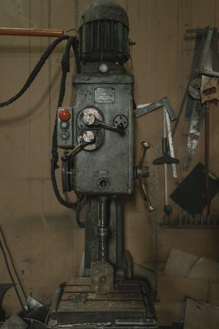
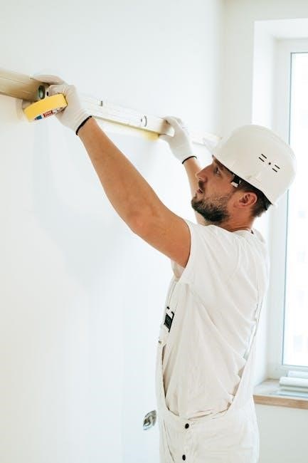
Proper Installation Procedures

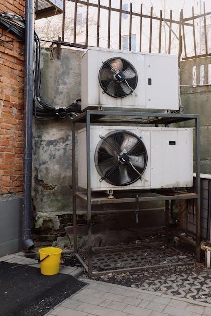
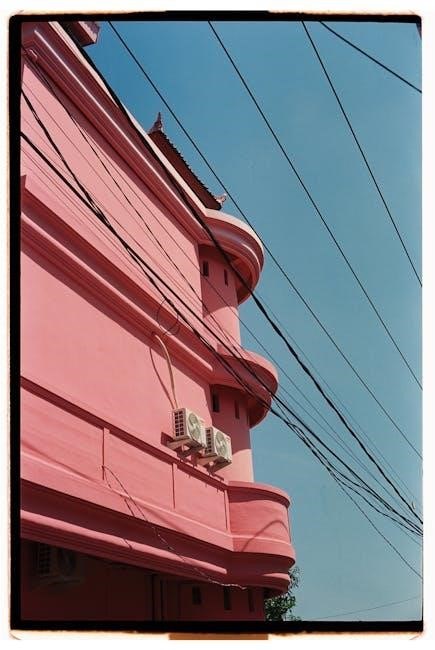
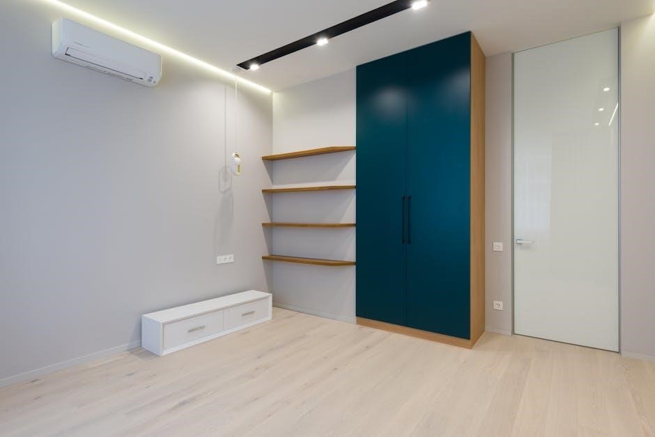
Successful installation of your Dometic marine air conditioner requires meticulous adherence to guidelines. Begin by selecting a structurally sound location capable of supporting the unit’s weight, ensuring adequate airflow around the condenser. Securely mount the unit, minimizing vibration with appropriate isolation materials.

Carefully plan ductwork, optimizing vent sizes and return air pathways for efficient circulation. Seal all connections to prevent air leakage and maintain cooling capacity. Prioritize proper drainage, establishing a clear path for condensate water to prevent buildup and potential damage. Double-check all mounting hardware and connections before proceeding to electrical and plumbing phases, guaranteeing a stable and reliable system.

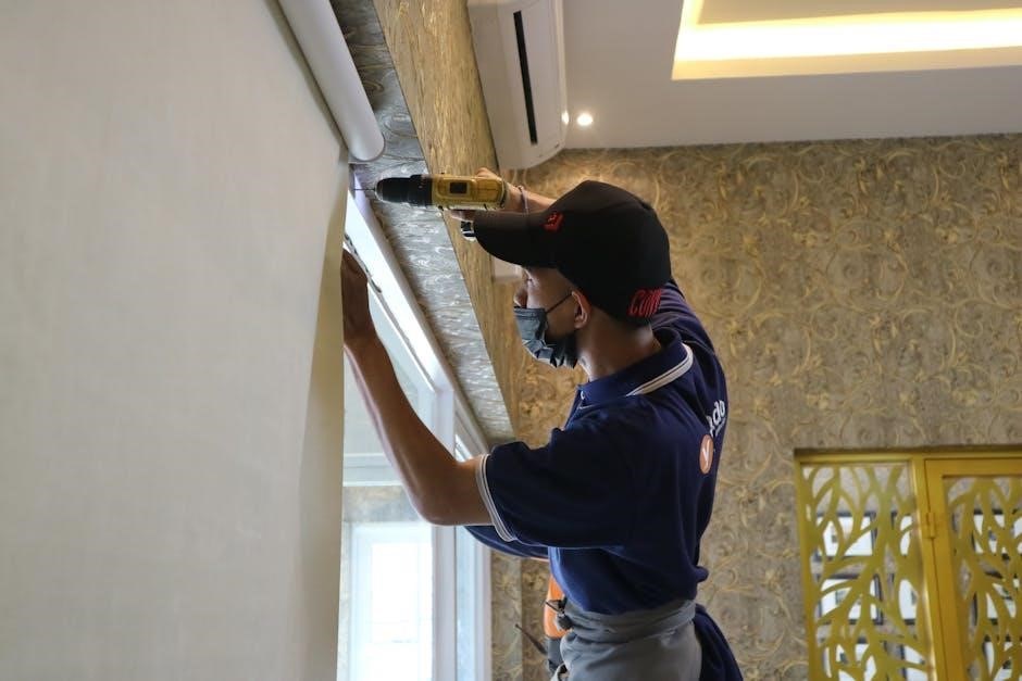
Electrical Connections & Wiring Diagrams

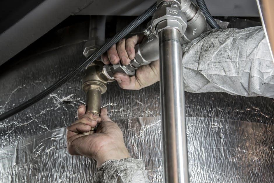
Correct electrical connections are crucial for safe and efficient Dometic AC operation. Always disconnect shore power before commencing any wiring work. Refer to the unit’s specific wiring diagram, ensuring accurate identification of power, ground, and control wires. Utilize marine-grade wiring of the appropriate gauge, capable of handling the unit’s current draw.

Employ secure connections, utilizing properly sized terminals and weatherproof connectors. A dedicated circuit breaker, sized according to the AC unit’s specifications, is essential for overload protection. Verify proper grounding to prevent electrical shock hazards. Incorrect wiring can lead to malfunction or damage; professional assistance is recommended if unsure.

Water Intake & Discharge Considerations

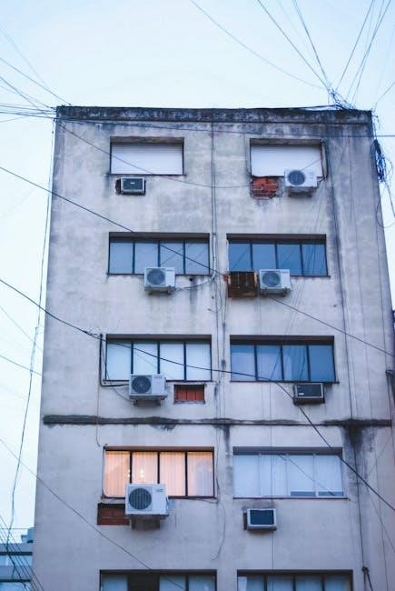
Dometic marine AC systems require a reliable source of seawater for cooling. Ensure the water intake strainer is free of debris to maintain adequate flow. Regularly inspect and clean the strainer lid, preventing overheating and pump damage. Discharge hoses must be securely connected and positioned to prevent back-siphoning of seawater into the unit.

Verify the water pump operates efficiently, checking for proper prime and flow rate. Consider the boat’s speed and sea conditions, as these can affect water intake. A restricted water supply will cause the unit to shut down; address any flow issues promptly to avoid compressor damage.

Operation & Control

Dometic AC operation involves adjusting the thermostat, fan speed, and selecting cooling or heating modes for optimal comfort and efficient climate control.

Thermostat Operation & Settings

Understanding your Dometic marine AC thermostat is crucial for comfortable operation. The thermostat controls the unit’s temperature, fan speed, and mode selection. Begin by powering on the thermostat and setting your desired temperature; lower numbers mean cooler air, and higher numbers indicate warmer air.

Ensure the thermostat is set to “Auto” or “Cool” for cooling, and “Heat” for heating. Fan speed settings typically include “Low,” “Medium,” and “High,” influencing airflow and energy consumption. Regularly check the thermostat’s display for error codes, which can indicate potential issues. Proper thermostat function ensures efficient and consistent climate control throughout your vessel, maximizing comfort and minimizing energy waste.

Fan Speed Control & Airflow Direction

Dometic marine AC systems offer adjustable fan speeds – Low, Medium, and High – to customize airflow and comfort. Lower speeds conserve energy and reduce noise, while higher speeds provide rapid cooling or heating. Many units feature adjustable vents allowing you to direct airflow precisely where needed within the cabin.

Proper airflow is vital for even temperature distribution. Regularly inspect vents for obstructions like debris or closed dampers. Ensure vents aren’t blocked by curtains or furniture. Measuring vent and return sizes is recommended for optimal performance. Adjusting airflow direction maximizes cooling efficiency and prevents cold or warm spots, enhancing overall comfort aboard your boat.

Cooling & Heating Modes Explained

Dometic marine AC units typically offer distinct cooling and heating modes. Cooling mode extracts heat from the cabin air, providing a refreshing environment in warmer climates. Heating mode reverses this process, generating warmth for cooler conditions – utilizing an integrated heat pump. Some models offer ‘Auto’ mode, intelligently switching between cooling and heating to maintain a set temperature;

Understanding these modes is crucial for efficient operation. Ensure the correct mode is selected based on the prevailing weather. Regularly check for proper operation of both cooling and heating functions. A malfunctioning heat pump can lead to inefficient heating or complete failure, requiring professional service for diagnosis and repair.

Maintenance & Cleaning

Regular maintenance, including air filter replacement and coil cleaning, ensures optimal performance and longevity of your Dometic marine AC system.

Air Filter Replacement & Cleaning

Maintaining clean air filters is crucial for efficient Dometic marine AC operation. Regularly check and replace or clean filters – typically every month with frequent use, or at least seasonally. Dirty filters restrict airflow, reducing cooling capacity and potentially causing the unit to freeze.

To clean reusable filters, gently vacuum loose debris, then wash with mild soap and water. Ensure they are completely dry before reinstalling. Replacement filters should match the specified size for your Dometic model. Accessing the filters usually involves removing a panel on the unit; consult your specific model’s manual for precise instructions. Proper filter maintenance extends the lifespan of your AC system and improves air quality onboard.

Coil Cleaning Procedures

Regular coil cleaning is essential for optimal Dometic marine AC performance. Over time, coils accumulate dust, salt spray, and debris, hindering heat transfer and reducing efficiency. Turn off power to the unit before cleaning. Use a soft brush attachment on a vacuum to remove loose particles.

For deeper cleaning, a commercially available coil cleaner (specifically designed for AC units) can be applied, following the product’s instructions carefully. Avoid harsh chemicals or abrasive cleaners. Rinse thoroughly with fresh water, ensuring no cleaner residue remains. Clean both the evaporator (indoor) and condenser (outdoor) coils for best results. This process improves cooling capacity and extends the unit’s lifespan.

Water Strainer Maintenance

Consistent water strainer maintenance is crucial for Dometic marine AC operation, preventing pump damage and ensuring efficient cooling. Regularly inspect the strainer basket for debris like seaweed, sand, and small objects. Clean the basket thoroughly, removing all obstructions.

Verify the strainer lid seals tightly to prevent water leakage. Check for good water flow through the strainer; a restricted flow indicates a blockage. Periodically inspect the pump for overheating, a sign of a clogged strainer. A well-maintained strainer ensures a consistent water supply to the AC unit, maximizing performance and preventing costly repairs.

Troubleshooting Common Issues

Common problems include units failing to power on, lack of cooling, freezing, pump malfunctions, capacitor failures, and thermostat errors—decode messages for fixes.

Unit Won’t Turn On: Power Supply Checks

If your Dometic AC unit isn’t powering on, begin with fundamental power supply checks. Verify the circuit breaker dedicated to the AC unit hasn’t tripped; reset if necessary. Inspect the AC’s power cord for any visible damage or loose connections. Confirm the thermostat is set to a cooling or heating mode and isn’t in “off” position.

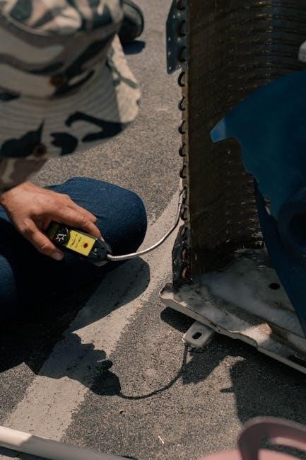
Check the voltage at the unit itself using a multimeter to ensure it’s receiving the correct power. A fried run capacitor, as seen in some cases, can also prevent startup – visually inspect for melting or bulging. If these initial steps don’t resolve the issue, further electrical component testing might be required by a qualified technician.

No Cooling: Refrigerant & Compressor Issues

If your Dometic marine AC is running but not producing cold air, refrigerant or compressor problems are likely culprits. Low refrigerant levels significantly reduce cooling capacity, requiring professional diagnosis and recharge – do not attempt this yourself. A failing compressor, the heart of the cooling system, will also prevent effective cooling.

Listen for unusual noises from the compressor; clicking or humming without cooling suggests a malfunction. Inspect the condenser and evaporator coils for ice buildup, indicating potential refrigerant issues. Professional service is essential for checking refrigerant levels and diagnosing compressor functionality, as these involve specialized tools and expertise.

Unit Freezing Up: Causes & Solutions

A frozen Dometic marine AC unit typically indicates restricted airflow or low refrigerant. Dirty air filters are a common cause, hindering air circulation across the evaporator coil. Inspect and replace or clean filters regularly. Reduced water flow through the condenser coil can also lead to freezing, so verify proper water intake and strainer cleanliness.

If icing occurs, immediately turn off the AC unit and allow it to thaw completely. Address the underlying cause – clean filters, check water flow – before restarting. Persistent freezing suggests a refrigerant leak or compressor issue, requiring professional diagnosis and repair. Ignoring this can damage the unit.

Water Pump Problems & Troubleshooting

Dometic marine AC systems rely on a water pump to circulate cooling water. A failing pump often presents as noisy operation or a loss of prime, indicated by warm air. Verify the pump runs efficiently and isn’t overheating. Check for obstructions in the water intake line and strainer lid, ensuring good water flow.

If the pump is noisy but running, damaged ball bearings or housing are likely culprits, requiring replacement. A pump that doesn’t run at all could indicate electrical issues – check the power supply and wiring. Regular maintenance, including strainer cleaning, prevents many pump problems.

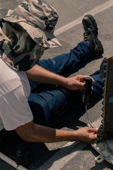
Capacitor Failure & Replacement

Capacitors are crucial for Dometic AC start-up and operation; failure manifests as the unit not turning on or humming without starting. A fried capacitor often shows visible signs of melting or bulging. Replacement is a relatively straightforward repair, but always disconnect power before proceeding.

Supco capacitors are frequently recommended replacements. Ensure the new capacitor has the same microfarad (µF) rating as the original. Carefully discharge the old capacitor before removal, and securely connect the wires to the new one. Incorrect wiring can cause further damage. Safety first – if unsure, consult a qualified technician.

Thermostat Malfunctions & Diagnosis

Thermostat issues can prevent your Dometic AC from functioning correctly, leading to inconsistent temperatures or a complete lack of response. Begin by verifying the thermostat’s power supply and settings. A faulty thermostat might display incorrect temperatures or fail to register changes. Check wiring connections for looseness or corrosion, as these can disrupt the signal.

If the thermostat appears unresponsive, try resetting it or replacing the batteries (if applicable); Decoding thermostat messages, as suggested in troubleshooting guides, is vital. If problems persist, a professional diagnosis is recommended to determine if the thermostat itself needs replacement.

Error Codes & Their Meanings

Dometic marine AC systems utilize error codes to signal specific malfunctions, aiding in efficient troubleshooting. These codes, displayed on the thermostat or control panel, pinpoint the source of the problem, ranging from sensor failures to compressor issues. Consulting your unit’s specific manual is crucial for accurate interpretation.

Common codes might indicate low refrigerant, overheating, or pump failures. Understanding these codes allows for targeted repairs, potentially avoiding unnecessary service calls. Documenting the error code before contacting a technician can expedite the diagnostic process and ensure a quicker resolution to your AC issue.

Advanced Troubleshooting

Professional service is required for checking refrigerant levels, compressor diagnostics, and electrical component testing within your Dometic marine AC system.

Checking Refrigerant Levels (Professional Service Required)

Refrigerant level checks are a complex procedure and must be performed by a qualified HVAC/R technician. Attempting to handle refrigerant yourself is dangerous and potentially illegal. Low refrigerant levels indicate a leak, which needs professional diagnosis and repair. Technicians utilize specialized gauges and equipment to accurately measure refrigerant pressure and identify leak locations;

They will then evacuate the system, repair the leak, and recharge it with the correct type and amount of refrigerant, as specified by the Dometic unit’s documentation. Improper refrigerant charge can severely damage the compressor and reduce cooling efficiency. Always prioritize safety and rely on certified professionals for this critical maintenance task.

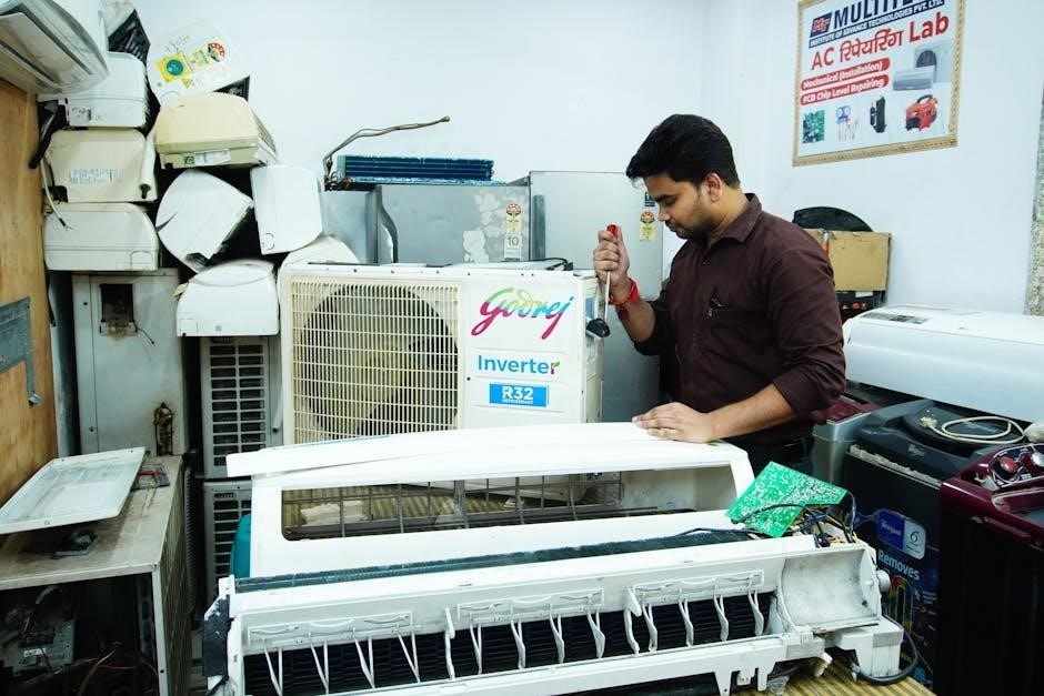
Compressor Diagnostics (Professional Service Required)

Compressor diagnostics require specialized tools and expertise, demanding a qualified HVAC/R technician. Symptoms like unusual noises, overheating, or failure to start indicate potential compressor issues. Technicians use multimeters to check winding resistance and voltage, assessing electrical integrity. They also perform amp draw measurements to verify proper operation under load.

Further diagnostics involve pressure testing to evaluate compressor pumping capacity. A failing compressor often necessitates replacement, a task best left to professionals due to the complexity and potential for refrigerant handling. Attempting self-repair can lead to further damage and safety hazards; always prioritize professional service.

Electrical Component Testing (Professional Service Required)

Electrical component testing within the Dometic AC system demands a skilled technician’s expertise and appropriate safety measures. This includes verifying the functionality of the run capacitor – a common failure point – using a capacitance meter. Technicians also inspect contactors for burned or pitted contacts, ensuring proper switching.

Voltage checks are crucial at various points to identify wiring faults or power supply issues. Furthermore, testing the control board’s components requires specialized knowledge. Incorrect testing or repair attempts can create safety hazards or cause further damage. Always rely on a qualified professional for these procedures.

Safety Precautions

Prioritize electrical safety and refrigerant handling; always disconnect power before servicing and heed warnings regarding potential hazards during Dometic AC work;

Electrical Safety Guidelines

Always disconnect shore power and any battery connections before attempting any electrical work on your Dometic marine air conditioner. Verify complete power isolation using a reliable voltage tester. Never work on electrical components while standing in water or on a wet surface. Ensure all wiring connections are secure and properly insulated to prevent shorts and potential fire hazards.

Inspect wiring for damage – cracks, fraying, or corrosion – and replace compromised wires immediately. When replacing components like capacitors, use only manufacturer-approved parts with the correct voltage and capacitance ratings. Improperly installed electrical components can lead to malfunctions and safety risks. If you are uncomfortable performing electrical work, consult a qualified marine electrician.

Refrigerant Handling Safety

Refrigerant handling requires specialized knowledge and equipment; Dometic strongly advises against attempting any refrigerant service yourself. Contact a certified marine refrigeration technician for any refrigerant-related issues, such as leaks or low refrigerant levels. Refrigerant can cause frostbite and other health hazards upon contact with skin or inhalation.

Never release refrigerant into the atmosphere – it’s harmful to the environment and illegal. Proper recovery and disposal procedures must be followed by a qualified technician. Be aware of the potential for refrigerant burns when working near compressor lines. Always wear appropriate safety glasses and gloves when near refrigeration components, even during diagnostics performed by a professional.

General Safety Warnings

Always disconnect shore power and/or the boat’s DC power before performing any maintenance or troubleshooting on your Dometic marine air conditioner. Water and electricity are a dangerous combination; ensure all electrical connections are dry. Never operate the unit with access panels removed, as moving parts pose a safety risk.

Inspect wiring regularly for damage and replace any frayed or cracked wires immediately. Be cautious of sharp edges on the unit’s housing and components. Do not modify the air conditioner in any way, as this could compromise its safety and performance. If you smell a burning odor, immediately shut down the system and investigate the source.

Parts & Accessories

Replacement parts and compatible accessories for your Dometic AC are crucial for maintaining optimal performance and longevity of the system.

Finding Replacement Parts

Locating genuine Dometic replacement parts is essential for ensuring the continued efficiency and reliability of your marine air conditioning system. Several avenues exist for sourcing these components. Authorized Dometic dealers, both online and brick-and-mortar stores, offer a comprehensive selection and expert advice. Websites specializing in marine HVAC parts also provide a convenient option, often with detailed parts diagrams to aid in identification.

When ordering, always have your unit’s model number readily available to guarantee compatibility. Common replacement parts include run capacitors (like Supco caps), air filters, water strainers, and occasionally, pumps. Prioritize genuine Dometic parts to avoid compromising performance or voiding your warranty. Be cautious of generic alternatives, as quality can vary significantly.

Compatible Accessories

Enhance your Dometic marine AC system’s performance and longevity with compatible accessories. Essential additions include high-quality air filters, readily available for replacement to maintain optimal airflow and cooling efficiency. Consider a robust water strainer to protect the pump from debris, preventing potential blockages and overheating. Ducting kits, sized appropriately for your vents and returns, ensure efficient air distribution throughout the vessel.

For advanced monitoring, explore smart thermostats offering remote control and energy usage tracking. Protective covers safeguard the unit during periods of non-use. Regularly inspecting and maintaining these accessories contributes significantly to the overall health and lifespan of your Dometic air conditioning system.

Warranty Information

Dometic provides warranty details for its marine AC units; product registration is crucial to validate coverage and access support efficiently.

Dometic Warranty Details

Dometic stands behind the quality of its marine air conditioning systems with a comprehensive warranty program. The standard warranty typically covers defects in materials and workmanship for a specified period from the original date of purchase. This coverage generally includes parts and, in some cases, labor costs associated with repairing or replacing defective components.

However, the specific terms and duration of the warranty can vary depending on the model and the region where the product was purchased. It’s essential to review the warranty documentation included with your unit for precise details. Certain conditions may void the warranty, such as improper installation, misuse, neglect, or unauthorized modifications. Maintaining proper maintenance records, like filter changes and coil cleaning, can also be beneficial when filing a warranty claim.

Registering Your Product

Registering your Dometic marine air conditioner is a crucial step to ensure seamless warranty service and access to important product updates. Online registration is typically available through the official Dometic website, requiring your model number, serial number, and proof of purchase. This process validates your ownership and establishes the purchase date for warranty purposes.

Registration also allows Dometic to notify you of any safety recalls, software updates, or new product information relevant to your specific unit. Keeping your contact information current within the Dometic system streamlines communication and facilitates efficient support should you ever require assistance. Retain your registration confirmation as proof of submission.

mercury mariner outboard manual

Mercury Mariner Outboard Manual: A Comprehensive Guide

Navigating your Mercury Mariner requires a dedicated resource; this manual, spanning models like the 1989 15Hp and 25Hp, unlocks features and ensures optimal performance.

Mercury Mariner outboards have a long-standing reputation for reliability and performance on the water, serving boaters for decades. These engines, ranging in horsepower from compact 15Hp models to more powerful options, are designed for a diverse range of applications – from small fishing boats and inflatables to larger recreational vessels. Understanding the specifics of your particular Mariner engine is crucial for safe and efficient operation.

This is where a dedicated owner’s or service manual becomes invaluable. Whether you’ve recently acquired a classic 1989 model or a newer version, accessing the correct documentation provides a detailed overview of the engine’s features, functionality, and maintenance requirements. Properly utilizing the manual ensures you can maximize your boating experience and maintain the longevity of your Mercury Mariner outboard.

Understanding Manual Importance

A Mercury Mariner outboard manual isn’t merely a collection of pages; it’s a vital tool for responsible ownership. It provides critical insights into the engine’s operation, safety precautions, and maintenance schedules, directly impacting performance and lifespan. Ignoring the manual can lead to improper operation, potentially causing damage or even hazardous situations on the water.

Specifically, manuals detail how to make the most of your product, offering a comprehensive overview of features. Whether it’s a user manual for a new owner or a service manual for detailed repairs, understanding the information within is paramount. Regular review ensures you’re equipped to address issues proactively, preventing minor problems from escalating into costly repairs and keeping your Mariner running smoothly for years to come.

Manual Types & Availability

Discover the distinctions between owner’s and service manuals, and explore options for locating the correct guide – both in print and digital formats – today!

Owner’s Manual vs. Service Manual

Understanding the difference between an owner’s manual and a service manual is crucial for Mercury Mariner outboard maintenance. The owner’s manual provides a foundational overview, detailing basic operation, safety precautions, and routine maintenance tasks like checking fluid levels or replacing a fuel filter. It’s designed for the everyday user, offering guidance on maximizing the outboard’s lifespan through preventative care.

Conversely, a service manual is a comprehensive, in-depth resource intended for qualified mechanics. It includes detailed diagrams, troubleshooting procedures, repair instructions, and specifications for nearly every component of the outboard. Tasks covered in a service manual extend to complex repairs like carburetor rebuilding, lower unit servicing, or cylinder head removal. While an owner can attempt some procedures from a service manual, it’s generally recommended to leave intricate repairs to professionals equipped with the proper tools and expertise. Essentially, the owner’s manual teaches you how to use the outboard, while the service manual teaches you how to fix it.

Finding the Correct Manual (Year & HP)

Locating the precise manual for your Mercury Mariner outboard is paramount, as components and procedures vary significantly between years and horsepower ratings. A manual designed for a 1989 15Hp model will differ substantially from one for a newer, higher-horsepower engine. Always verify that the manual explicitly states the correct year and HP of your outboard before attempting any maintenance or repairs.

Resources for finding the correct manual include the official Mercury Marine website, online marketplaces specializing in marine manuals, and dedicated outboard motor forums. When searching, be precise with your engine’s details – year, horsepower, and even the specific model number if available. Incorrect manuals can lead to improper procedures, potentially causing damage to your engine or even personal injury. Double-checking compatibility is a small step that can save considerable trouble and expense down the line.

Digital Manuals & Online Resources

Accessing information for your Mercury Mariner outboard has become increasingly convenient with the proliferation of digital manuals and online resources. While physical copies remain valuable, digital versions offer portability and searchability, allowing quick access to specific information when needed. Numerous websites host downloadable manuals, often available for free or a small fee.

Furthermore, online forums dedicated to Mercury Mariner outboards are treasure troves of knowledge, with experienced owners sharing troubleshooting tips, repair guides, and even scanned copies of manuals. YouTube channels also provide visual demonstrations of maintenance procedures. However, always cross-reference information from online sources with official Mercury documentation to ensure accuracy and safety. Utilizing these digital tools can significantly enhance your ability to maintain and repair your outboard effectively.

Essential Components & Systems

Understanding the Mariner’s fuel, ignition, and cooling systems—along with steering and shift mechanisms—is crucial for effective maintenance and troubleshooting of your outboard.

Fuel System Overview (Carburetor & Fuel Pump)

The Mercury Mariner’s fuel system relies on a precise interplay between the carburetor and fuel pump to deliver a consistent fuel-air mixture for optimal combustion. The fuel pump draws fuel from the tank, ensuring a steady supply to the carburetor.

Carburetors meticulously blend fuel with air, adjusting the mixture based on engine demand – idle, mid-range, or full throttle. Regular inspection and cleaning of the carburetor are vital, as deposits can restrict fuel flow and impair performance.

Fuel lines and filters must be checked for cracks, leaks, or blockages. A clogged fuel filter restricts fuel delivery, leading to starting difficulties or reduced power. Understanding this system allows for effective diagnosis of fuel-related issues, ensuring reliable operation and preventing potential damage.

Ignition System Explained

The Mercury Mariner’s ignition system is crucial for initiating combustion within the engine cylinders. It typically comprises components like the flywheel magneto, ignition coil, condenser, and spark plugs. The flywheel magneto generates electricity as the engine rotates, providing the power source for ignition.

The ignition coil amplifies this voltage, creating a high-voltage pulse sent to the spark plugs. A properly functioning condenser stabilizes the ignition circuit, ensuring a strong spark. Spark plugs then ignite the fuel-air mixture, driving the piston and powering the outboard.

Regular inspection of these components is vital. Worn spark plugs, a faulty coil, or a damaged condenser can lead to misfires, starting problems, or reduced engine performance. Maintaining a robust ignition system guarantees reliable starts and efficient operation.

Cooling System Details (Water Pump & Thermostat)

Mercury Mariner outboards rely on a robust cooling system to prevent overheating and ensure longevity. This system centers around a water pump, responsible for circulating water throughout the engine block and exhaust passages. The water pump’s impeller draws water in and forces it through cooling channels, absorbing heat.

A thermostat regulates engine temperature by controlling the flow of coolant. When the engine reaches its optimal operating temperature, the thermostat opens, allowing coolant to circulate through the exhaust system, dissipating heat.

Regularly inspect the water pump impeller for wear or damage, and verify the thermostat functions correctly. A failing water pump or a stuck thermostat can quickly lead to overheating, potentially causing severe engine damage. Consistent maintenance is key.

Steering & Shift Mechanisms

Mercury Mariner outboards employ various steering and shift mechanisms, depending on the model year and horsepower. Common steering systems include tiller arms for smaller engines and cable-operated steering for larger ones. Understanding your specific system is crucial for safe and responsive boat handling.

Shift mechanisms typically involve a shift cable connecting the control lever to the lower unit. This cable engages or disengages gears, allowing for forward, neutral, and reverse operation. Proper cable adjustment is vital for smooth and accurate shifting.

Regularly inspect steering linkages and shift cables for wear, corrosion, or damage. Lubricate moving parts to ensure smooth operation. Addressing any issues promptly will prevent steering or shifting problems while on the water, enhancing safety and control.

Maintenance Procedures

Consistent upkeep, including oil changes, spark plug checks, and fuel filter replacements, is paramount for extending the life and reliability of your Mariner outboard.

Regular Maintenance Schedule

Establishing a consistent maintenance schedule is crucial for the longevity and peak performance of your Mercury Mariner outboard. After each use, flush the cooling system with fresh water to remove salt and debris, preventing corrosion. Every 10 hours of operation, inspect the propeller for damage and ensure proper lubrication of all moving parts.

A more thorough inspection should occur every 50 hours, including checking the fuel lines, connections, and filter for leaks or blockages. Annually, or every 100 hours (whichever comes first), perform a complete oil change for both the engine and gearcase, replacing the spark plugs and inspecting the ignition system. Don’t neglect the steering and shift linkages, ensuring smooth and responsive operation. Following this schedule diligently will minimize downtime and maximize your enjoyment on the water, safeguarding your investment for years to come.

Oil Change Procedures (Gearcase & Engine)

Performing regular oil changes is vital for both the engine and gearcase of your Mercury Mariner. For the engine, warm it up briefly, then remove the drain plug, allowing the old oil to fully drain. Replace the plug with a new gasket and refill with the manufacturer’s recommended oil type and quantity.

For the gearcase, locate the fill and drain plugs – typically on the lower unit. With the boat in neutral, remove the drain plug first, followed by the fill plug to allow air to enter. Once drained, replace the drain plug and slowly fill with gearcase oil until it appears at the fill hole. Replace the fill plug securely. Always dispose of used oil responsibly, adhering to local regulations. Consistent oil changes ensure optimal lubrication and protect vital components.

Spark Plug Replacement & Inspection

Maintaining optimal spark plug condition is crucial for efficient engine combustion. Begin by disconnecting the spark plug wires, noting their positions for correct reinstallation. Use a spark plug socket to carefully remove each plug, inspecting the electrodes for wear, fouling, or damage. A properly gapped plug ensures optimal spark.

To replace, select the correct spark plug specified for your Mercury Mariner model. Gap the new plug to the manufacturer’s specifications using a spark plug gapping tool. Carefully thread the new plug into the cylinder head, tightening to the recommended torque; Reconnect the spark plug wires, ensuring a secure fit. Regular inspection and replacement contribute to smooth operation and prevent performance issues.

Fuel Filter Replacement

Protecting your Mercury Mariner’s fuel system requires periodic fuel filter replacement. Locate the fuel filter, typically found in the fuel line between the fuel tank and the carburetor. Before disassembly, relieve fuel system pressure to prevent spills. Carefully disconnect the fuel lines from the filter, using appropriate tools to avoid damage.

Install the new fuel filter, ensuring correct flow direction as indicated by the arrow on the filter housing. Securely reconnect the fuel lines, verifying a tight seal to prevent leaks; After replacement, prime the fuel system by operating the fuel pump. Regularly changing the fuel filter prevents contaminants from reaching the carburetor, ensuring optimal engine performance and longevity.

Troubleshooting Common Issues

Diagnosing problems like starting failures, poor performance, overheating, or electrical faults is crucial; this section provides basic checks and solutions for your Mariner.

Engine Won’t Start – Diagnosis

When your Mercury Mariner refuses to start, a systematic approach is essential. First, verify the fuel supply – is the tank full and the fuel line unobstructed? Next, inspect the spark plugs; are they clean, properly gapped, and firing correctly? A weak spark indicates potential ignition system issues, possibly a faulty coil or magneto.

Check the kill switch; ensure it’s not engaged. Confirm the propeller spins freely, ruling out internal engine seizure. Low compression can also prevent starting, requiring further investigation. Don’t overlook the simple things – a discharged battery or corroded connections can halt operation. Utilizing a spark tester and compression gauge will aid in pinpointing the root cause, allowing for targeted repairs and a swift return to the water.

Poor Performance – Causes & Solutions

Experiencing diminished power from your Mercury Mariner? Several factors could be at play. A clogged fuel filter restricts fuel flow, leading to sluggish response. Dirty or worn spark plugs create incomplete combustion, reducing efficiency. Inspect the carburetor for debris or varnish buildup, hindering proper fuel-air mixture.

Additionally, a failing fuel pump struggles to deliver adequate fuel pressure. Compression loss within the cylinders significantly impacts performance. Check the propeller for damage – a bent or nicked blade reduces thrust. Regularly inspecting and maintaining these components is crucial. Addressing these issues, from simple cleaning to component replacement, will restore your Mariner’s optimal power and ensure a smooth boating experience.

Overheating Problems – Identification & Fixes

Overheating is a serious concern for Mercury Mariner outboards, potentially causing significant engine damage. Identifying overheating early is vital; watch for the temperature warning light or steam emanating from the engine. A primary culprit is often a malfunctioning water pump, failing to circulate coolant effectively. Inspect the thermostat for proper operation – a stuck thermostat restricts coolant flow.

Furthermore, a blocked cooling passage, often due to corrosion or debris, hinders heat dissipation. Ensure the water intake is clear of obstructions. Regularly flushing the cooling system prevents buildup. If overheating persists, inspect the cylinder head gasket for leaks. Promptly addressing these issues prevents catastrophic engine failure and extends the life of your Mariner.

Electrical System Faults – Basic Checks

Electrical issues can quickly disable your Mercury Mariner. Begin with a visual inspection of all wiring, searching for corrosion, loose connections, or damaged insulation. Check the battery terminals for cleanliness and tightness; a weak connection hinders starting. Utilize a multimeter to test the battery voltage – it should be within the manufacturer’s specified range.

Inspect the fuses and circuit breakers; a blown fuse indicates a short circuit. Examine the ignition system components, including the coil and spark plugs, for proper functionality. Don’t overlook the kill switch, ensuring it’s not accidentally engaged. Addressing these basic checks often resolves common electrical faults, restoring your outboard’s operation and preventing further complications.

Repair & Overhaul Information

Detailed guides cover lower unit service, carburetor rebuilding, cylinder head work, and propeller maintenance – essential for restoring peak Mercury Mariner performance.

Lower Unit Service & Repair

The lower unit, housing the gears and propeller shaft, demands meticulous attention. Regular servicing prevents costly failures and ensures smooth operation. Begin by disconnecting the shift linkage and removing the lower unit, carefully noting the alignment marks. Inspect the gears for wear or damage, paying close attention to the forward, reverse, and pinion gears.

Check the water pump impeller for cracks or deterioration – a faulty impeller leads to overheating. Replace the seals and O-rings during reassembly, using marine-grade grease to lubricate the components. Proper gear case oil level is crucial; replenish with the manufacturer’s recommended fluid.

Always torque the mounting bolts to the specified values to prevent leaks and ensure a secure connection. Addressing minor issues promptly can prevent major overhauls, extending the life of your Mercury Mariner’s lower unit.

Carburetor Rebuild Guide

A carburetor rebuild restores optimal fuel delivery, addressing issues like rough idling or poor performance. Begin by carefully disassembling the carburetor, noting the position of all jets, needles, and linkages. Soak the components in carburetor cleaner to dissolve varnish and deposits. Inspect each part for wear or damage, replacing worn needles, seats, and gaskets.

Pay close attention to the float level, adjusting it according to the manufacturer’s specifications. Clean the jets thoroughly using fine wire, ensuring they are free of obstructions. Reassemble the carburetor, lubricating moving parts with a light oil.

Proper adjustment of the idle mixture and high-speed screws is vital for smooth operation; consult your manual for specific settings. A well-maintained carburetor ensures efficient fuel combustion and reliable engine performance.

Cylinder Head Removal & Inspection

Cylinder head removal is a complex procedure, requiring careful attention to detail. Begin by disconnecting the spark plugs and exhaust manifold. Loosen the head bolts in a crisscross pattern to prevent warping. Once removed, inspect the cylinder head for cracks, especially around the combustion chambers and valve seats.

Check the valve guides and valve faces for wear or damage, and consider valve replacement if necessary. Inspect the head gasket for signs of leakage or deterioration. Ensure the cylinder head surface is flat using a straightedge; machining may be required if warping is present.

Proper torque specifications are crucial during reassembly; consult your manual. A damaged cylinder head can lead to compression loss and engine failure.

Propeller Maintenance & Replacement

Regular propeller inspection is vital for optimal performance and preventing damage. Check for bent blades, nicks, or cracks, which can significantly reduce efficiency and create vibration. Inspect the shear pins for corrosion or damage; these are designed to break before causing more serious harm to the drivetrain.

When replacing a propeller, ensure it matches your engine’s horsepower and gear ratio. Using the incorrect propeller can strain the engine and reduce speed. Remove the retaining nut and washer, then slide the old propeller off the shaft.

Lubricate the shaft before installing the new propeller, and tighten the retaining nut to the manufacturer’s specified torque. Always carry a spare shear pin and propeller.

weider 2980 x manual

Weider 2980 X Manual: A Comprehensive Guide

This guide provides detailed instructions, parts lists, safety precautions, and workout routines for the Weider 2980 X home gym system, ensuring optimal use.

The Weider 2980 X is a popular home gym system designed for comprehensive full-body workouts. This manual serves as your primary resource for understanding, assembling, operating, and maintaining this versatile fitness equipment. Whether you’re a seasoned fitness enthusiast or just beginning your journey, this guide will provide the necessary information to maximize your workout potential and ensure safe usage.

This system boasts a robust construction and a variety of exercise options, catering to diverse fitness levels. Before commencing any exercise program, carefully review the safety precautions outlined within this manual. Familiarize yourself with all components and their functions, utilizing the detailed parts list and diagrams provided. Proper assembly and regular maintenance are crucial for longevity and optimal performance.

Understanding the Weider 2980 X System

The Weider 2980 X functions as a multi-gym, integrating various exercise stations into a single unit. It features a weight stack system allowing adjustable resistance for diverse exercises targeting all major muscle groups. Understanding the interconnectedness of these stations – including the chest press, leg developer, and bicep curl – is key to effective training.

The system’s design prioritizes biomechanical efficiency, promoting proper form and minimizing strain. Familiarize yourself with the range of motion for each exercise and the corresponding weight settings. This manual details how to safely adjust the weight stack and utilize the included exercise chart for guided workouts. Consistent use, coupled with proper understanding, unlocks the full potential of the 2980 X.

Product Features and Specifications

The Weider 2980 X boasts a robust steel frame, adjustable weight stack, and multiple workout stations, delivering a comprehensive and versatile home gym experience.

Key Features of the Weider 2980 X

The Weider 2980 X stands out with its high and low pulley systems, enabling a diverse range of exercises targeting various muscle groups. Its weight stack, adjustable up to a substantial capacity, caters to users of all fitness levels; The inclusion of a leg developer and crunch station further expands workout possibilities.

Constructed with a durable steel frame, the 2980 X ensures stability and longevity. Comfortable, contoured seating enhances user experience during extended workout sessions. The system’s design prioritizes versatility, allowing for both strength training and cardio-focused routines. Detailed exercise charts, often available as a PDF, guide users through proper form and technique. Replacement parts, like the BASE (267646) and STABILIZER (267638), are readily accessible, ensuring continued functionality.

Technical Specifications: Dimensions & Weight Capacity

The Weider 2980 X boasts impressive specifications designed for effective home workouts. While precise dimensions vary slightly, expect a footprint of approximately 79” length x 48” width x 82” height. This substantial size accommodates a full range of motion for various exercises.

The system supports a maximum user weight capacity of 300 lbs, ensuring stability and safety for a wide range of individuals. The weight stack typically offers up to 80 lbs of resistance, adjustable in increments to suit different strength levels. It’s crucial to verify these specifications with the official manual or Weider’s website, referencing your specific model/serial number for accurate details. Proper assembly, utilizing all 88 parts, is vital to achieving these performance standards.

Assembly and Setup

Proper assembly, utilizing the 88 parts and included diagram, is crucial for safe and effective use of the Weider 2980 X home gym system.

Unboxing and Parts Inventory

Carefully unpack all components from the shipping carton, checking them against the detailed parts list (containing 88 unique parts) to ensure everything is present. Lay out all items on a protected surface to prevent scratches or damage during assembly.

Refer to the diagram provided within the manual to visually identify each part. Pay close attention to smaller components like M8 and M10 locknuts, washers, and button screws – these are easily misplaced.

Verify quantities match the parts list; discrepancies should be reported to customer support immediately. Note the BASE (part 267646) and STABILIZER (part 267638) as key structural elements. A thorough inventory now will save time and frustration later in the assembly process.

Step-by-Step Assembly Instructions

Begin by attaching the BASE (267646) and STABILIZER (267638) components, utilizing M12 nuts and large washers as indicated in the diagram. Ensure proper alignment before fully tightening. Proceed systematically through each stage, referencing the visual guide for correct part placement and fastener types.

Pay close attention to the order of assembly; skipping steps can lead to instability or require disassembly. Use the appropriate tools (see ‘Tools Required for Assembly’) and avoid over-tightening bolts, which could damage threads.

Double-check connections after each step to confirm secure fastening. A well-executed assembly guarantees a safe and effective workout experience with your Weider 2980 X system.

Tools Required for Assembly

Successful assembly of your Weider 2980 X necessitates a few essential tools. A standard adjustable wrench is crucial for tightening various nuts and bolts, including M8, M10, and M12 sizes. A socket wrench set, encompassing multiple sizes, will expedite the process and provide greater leverage.

A Phillips head screwdriver is needed for securing certain components, while a rubber mallet can assist with gently aligning parts without causing damage. Consider having a level handy to ensure the gym is stable and balanced on the floor.

Finally, work gloves are recommended to protect your hands during assembly. Having these tools prepared beforehand will streamline the setup and ensure a smooth, frustration-free experience.

Parts List and Identification

This section details all 88 components of the Weider 2980 X, utilizing diagrams for easy identification and providing part numbers for replacements.

Detailed Parts List (88 Parts)

The Weider 2980 X system comprises 88 distinct parts, each crucial for functionality and user safety. This comprehensive list, referencing the model WESY1938.0, includes items like the BASE (part 267646), currently priced at $292.49, and the STABILIZER (part 267638).

Further components encompass various nuts – M8 Locknut (58 qty), M10 Locknut (56 qty), M12 Nut (82 qty) – alongside washers (Large Washer 78 qty, M10 Washer 57 qty). Also included are M10 x 25mm Button screws and numerous other fasteners essential for secure assembly.

Accessing a complete parts list and diagram requires your equipment’s model/serial number. This detailed inventory ensures accurate identification when ordering replacements, maintaining the gym’s performance and longevity.

Identifying Parts Using the Diagram

Accurate part identification is vital for successful assembly and maintenance of your Weider 2980 X. The provided diagram serves as a visual key, correlating each component with a unique part number. This ensures you select the correct replacement when needed, avoiding compatibility issues.

Referencing the diagram alongside the detailed parts list (containing 88 parts) allows for precise matching. Locate the part in question on the diagram, then cross-reference it with the corresponding number in the list.

Having your equipment’s model/serial number readily available is crucial when accessing the complete diagram online, guaranteeing you’re viewing the correct version for your specific unit.

Common Replacement Parts: BASE (267646) & STABILIZER (267638)

The BASE (part number 267646) and STABILIZER (part number 267638) are frequently requested replacement parts for the Weider 2980 X. Due to their critical role in structural integrity, these components may experience wear and tear over time with consistent use.

The BASE provides the foundational support for the entire system, while the STABILIZER ensures rigidity and prevents unwanted movement during workouts. Regularly inspect these parts for cracks, damage, or loosening.

Current pricing for the BASE is approximately $292.49. When ordering, always verify compatibility with your specific Weider 2980 X model using the serial number for accurate part selection.

Exercise Chart and Workout Routines

Explore a comprehensive exercise chart (PDF available) and sample routines tailored for various muscle groups, maximizing your Weider 2980 X workout experience.

Weider 2980 X Exercise Chart PDF

Accessing the Weider 2980 X Exercise Chart in PDF format provides a visually detailed guide to performing exercises correctly and safely on your home gym. This chart illustrates proper form for each exercise, targeting specific muscle groups. It’s an invaluable resource for both beginners and experienced fitness enthusiasts.

The PDF chart typically includes clear diagrams and step-by-step instructions, ensuring you understand the correct technique to avoid injury and maximize results. You can easily download and print the chart for convenient access during your workouts. It’s designed to help you create a structured and effective fitness plan, utilizing all the capabilities of the Weider 2980 X system. Finding this resource online will significantly enhance your training experience.

Sample Workout Routines for Different Muscle Groups

The Weider 2980 X allows for versatile training, and pre-designed workout routines maximize its potential. These routines are categorized by muscle group – chest, back, legs, shoulders, and arms – offering balanced fitness development. Each routine details specific exercises, sets, repetitions, and rest periods, catering to varying fitness levels.

Beginner routines focus on foundational movements and lighter resistance, while advanced routines incorporate more challenging exercises and heavier weights. Utilizing these routines ensures proper muscle engagement and prevents plateaus. Remember to warm up before each workout and cool down afterward. Consistency is key; aim for at least three workouts per week to see noticeable improvements in strength and muscle tone. Adapt the routines to your individual needs and goals.

Adjusting the Weight System for Optimal Resistance

The Weider 2980 X’s weight system is designed for customizable resistance, crucial for progressive overload. Weight adjustments are typically made via a weight selector pin, allowing users to easily increase or decrease the load. Start with a weight that allows for proper form throughout the entire exercise range of motion. Gradually increase the weight as strength improves, ensuring controlled movements.

Proper weight selection prevents injury and maximizes muscle engagement. Avoid ego lifting – prioritize form over weight. The system accommodates various fitness levels, from beginners to experienced lifters. Regularly reassess your weight settings to maintain a challenging yet safe workout. Refer to the exercise chart for recommended weight ranges for each exercise.

Maintenance and Safety

Regular inspection of the Weider 2980 X is vital for safe operation; adhere to the maintenance schedule and always prioritize safety precautions during use.

Regular Maintenance Schedule

To ensure the longevity and safe operation of your Weider 2980 X, a consistent maintenance schedule is crucial. Monthly, inspect all bolts and screws, tightening any that have loosened during use. Carefully examine the cable system for any signs of fraying or wear, replacing cables immediately if damage is detected.

Every three months, clean the frame with a damp cloth and mild detergent, avoiding abrasive cleaners. Lubricate all pivot points with a silicone-based lubricant to maintain smooth operation. Annually, thoroughly inspect the weight plates and pulleys for damage, and consider replacing worn parts. Regularly check the stability of the base and stabilizer components, ensuring they remain securely fastened. Following this schedule will help prevent issues and maximize your workout experience.

Safety Precautions During Use

Prioritize safety when operating the Weider 2980 X. Always inspect the machine before each use, ensuring all parts are secure and functioning correctly. Never exceed the maximum weight capacity, and use appropriate weight plates for your fitness level. Maintain a firm grip on handles and attachments during exercises.

Be mindful of your surroundings, keeping children and pets away from the equipment during operation. Avoid wearing loose clothing that could get caught in moving parts. If you experience any pain or discomfort, stop exercising immediately. Familiarize yourself with the emergency stop mechanism and know how to use it. Proper form is essential; consult resources for correct exercise techniques to prevent injuries.

Troubleshooting Common Issues

If encountering resistance issues, verify proper weight plate loading and cable alignment. Squeaking noises often indicate a need for lubrication on pivot points or cables – use silicone-based lubricant. For stability concerns, ensure the unit is on a level surface and all bolts are tightened securely.

Cable fraying requires immediate replacement; do not continue use. If a part is missing or damaged, refer to the parts list and ordering information. Difficulty adjusting weight may stem from a faulty selector pin – inspect for damage. Always disconnect power before inspecting electrical components. If problems persist, consult Weider’s customer support for assistance and potential repair options;

Parts Availability and Ordering

Genuine Weider 2980 X replacement parts are readily available online and through authorized retailers, utilizing your model/serial number for accurate ordering.

Where to Find Replacement Parts

Locating replacement parts for your Weider 2980 X is straightforward. Several online retailers specialize in fitness equipment components, offering a wide selection of parts specifically for this model. A quick internet search using terms like “Weider 2980 X parts” will yield numerous options.

Authorized Weider retailers also carry replacement parts, ensuring authenticity and quality. Checking the official Weider website can direct you to approved vendors in your region. Furthermore, some fitness equipment repair services stock common replacement parts like the BASE (267646) and STABILIZER (267638).

Before ordering, always have your Weider 2980 X model and serial number readily available to guarantee compatibility and avoid incorrect purchases. Many websites offer parts diagrams to assist in identification.

Using the Model/Serial Number for Parts Identification

Your Weider 2980 X’s model and serial number are crucial for accurate parts identification. This information ensures you order components specifically designed for your system, preventing compatibility issues and frustrating returns. The model number, often “WESY1938.0”, distinguishes the general system, while the serial number provides unique details about your specific unit.

Locate the label typically found on the frame of the gym. When contacting retailers or using online parts finders, providing both numbers is highly recommended. Many websites request this information to display a tailored parts list and diagram for your machine.

Accurate identification streamlines the process, saving time and ensuring you receive the correct replacement parts for a successful repair.

Current Pricing for Common Parts

Replacement parts for the Weider 2980 X vary in price depending on the component and retailer. As of February 2024, a BASE (part #267646) typically costs around $292.49, while a STABILIZER (part #267638) is priced approximately at the same value. Smaller components like M8 Locknuts or M10 Washers are significantly cheaper, often costing just a few dollars each.

Pricing fluctuates based on supplier, shipping costs, and availability. Online retailers specializing in fitness equipment parts generally offer competitive rates. It’s advisable to compare prices from multiple sources before making a purchase.

Remember to factor in potential shipping fees when calculating the total cost of your replacement parts.

Weider Brand Information

Weider is dedicated to supporting fitness and health goals, setting high standards for quality in sports nutrition and equipment manufacturing.

Weider’s Commitment to Fitness

Weider has a long-standing commitment to empowering individuals on their fitness journeys. For decades, the brand has focused on providing innovative and accessible fitness solutions, ranging from nutritional supplements to comprehensive home gym systems like the 2980 X. This dedication stems from a belief that everyone deserves the opportunity to achieve their health and wellness aspirations.

The company consistently invests in research and development to create products that deliver tangible results. Weider strives to offer not just equipment, but a complete ecosystem of support, including workout guidance and resources. Their aim is to inspire and motivate users to embrace a healthier lifestyle, fostering a community centered around fitness and well-being. Quality and customer satisfaction remain paramount in their approach.

Weider Product Quality Standards

Weider upholds rigorous quality standards throughout the design and manufacturing of its fitness equipment, including the 2980 X. These standards encompass material selection, structural integrity, and performance testing. Each component undergoes scrutiny to ensure durability and reliability, meeting or exceeding industry benchmarks.

The company employs stringent quality control processes at every stage of production, from initial prototyping to final assembly. This includes comprehensive testing for weight capacity, stress resistance, and overall functionality. Weider prioritizes user safety, adhering to strict safety regulations and certifications. Their commitment extends to providing clear and accurate documentation, like the 2980 X manual, to facilitate proper usage and maintenance, ensuring a long-lasting and safe fitness experience.

Weider Support and Resources

Weider provides extensive support resources for 2980 X owners, aiming to maximize user satisfaction. Online Manual Access offers a readily available digital copy of the comprehensive manual, including parts diagrams and troubleshooting guides. Dedicated Customer Support Contact Information is available via phone and potentially email, assisting with inquiries and resolving issues promptly.

Furthermore, Weider’s website features frequently asked questions (FAQs) and potentially video tutorials demonstrating proper assembly, usage, and maintenance procedures. Access to Related Weider Products allows users to explore complementary fitness equipment. The availability of replacement parts, identified using the model/serial number, ensures the longevity of the 2980 X system, fostering a positive and supported fitness journey.

Additional Resources

Explore online manuals, direct customer support contacts, and discover related Weider fitness products to enhance your 2980 X experience fully.

Online Manual Access

Accessing the Weider 2980 X manual online offers a convenient and readily available resource for users. Should you misplace the physical copy, or prefer a digital format for easy searching and portability, numerous online platforms host the complete guide.

Many websites dedicated to fitness equipment provide downloadable PDF versions of the manual. Before downloading, ensure the source is reputable to guarantee the accuracy and completeness of the document. Having your model/serial number handy will streamline the search process, allowing you to quickly locate the correct manual version for your specific 2980 X system.

This digital accessibility ensures you always have the information needed for assembly, maintenance, safety, and effective workout routines at your fingertips.

Customer Support Contact Information

For dedicated assistance with your Weider 2980 X, reaching out to customer support is a valuable option. While specific contact details may vary, Weider generally provides support through multiple channels.

Typically, you can find contact information – including phone numbers and email addresses – on the official Weider Fitness website. Look for a “Support” or “Contact Us” section. Be prepared to provide your model and serial number when contacting support; this will help them quickly address your specific inquiry regarding the 2980 X manual or any related issues.

Additionally, some online retailers who sell the Weider 2980 X may offer their own customer support resources. Utilizing these avenues ensures prompt and effective resolution to any questions or concerns.

Related Weider Products

Beyond the Weider 2980 X, Weider offers a comprehensive range of fitness equipment designed to cater to diverse workout preferences and fitness levels. Exploring these options can enhance your overall home gym experience.

Consider the Weider Pro series, known for its robust construction and advanced features, providing a step up in functionality. Weider also manufactures various weight benches, dumbbells, and resistance training systems, allowing for customized workout routines.

For those seeking cardio options, Weider provides treadmills, elliptical trainers, and exercise bikes. Checking the official Weider Fitness website will reveal the latest product offerings and allow you to compare specifications and features to find the perfect complement to your 2980 X system.

dewalt dcst920 manual

DeWalt DCST920 Manual: A Comprehensive Guide

This guide provides detailed instructions for the DeWalt DCST920 string trimmer‚ offering access to the PDF manual‚ troubleshooting‚ and support resources.

The DeWalt DCST920 is a 20V MAX XR brushless cordless string trimmer designed for efficient and powerful yard maintenance. This manual serves as a comprehensive resource‚ unlocking the trimmer’s full potential for both novice and experienced users; It details installation‚ operation‚ and maintenance procedures‚ ensuring optimal performance and longevity.

Understanding the owner’s manual is crucial for safe and effective operation. The DCST920 boasts a lightweight design and adjustable features‚ making it versatile for various trimming tasks. Accessing the PDF manual provides detailed diagrams and specifications‚ while this guide offers a structured approach to maximizing your trimming experience.

Key Features and Specifications

The DeWalt DCST920 features a high-efficiency brushless motor‚ delivering up to 70% more runtime compared to brushed motors. It boasts a 13-inch cutting swath for increased productivity and includes an easy-load string head for quick line replacements; Powered by a 20V MAX XR Lithium Ion battery (sold separately)‚ it offers cordless convenience and portability.

Key specifications include a variable speed trigger for enhanced control‚ an adjustable cutting head for versatile trimming‚ and a lightweight design at only 8.5 lbs. The manual details battery compatibility charts‚ ensuring optimal performance. This trimmer is designed for tackling tough outdoor jobs with power and durability‚ as highlighted in the PDF manual.

Safety Instructions

Always read the DeWalt DCST920 manual for crucial safety warnings‚ proper usage guidelines‚ and battery safety information to prevent injury during operation.

General Safety Warnings

Prior to using the DeWalt DCST920‚ carefully review all safety instructions and warnings detailed within the user manual. Always wear appropriate personal protective equipment‚ including eye protection‚ hearing protection‚ and sturdy footwear‚ to minimize risks. Keep bystanders‚ especially children and pets‚ a safe distance away from the operating area.

Inspect the trimmer before each use‚ ensuring all parts are securely fastened and in good working condition. Never operate the trimmer with damaged components. Be aware of your surroundings and potential hazards‚ such as hidden objects or uneven terrain. Avoid using the trimmer in wet or damp conditions‚ and never attempt to modify the tool in any way.

Always disconnect the battery pack before making any adjustments‚ changing accessories‚ or performing maintenance. Store the battery pack and charger in a cool‚ dry place‚ away from direct sunlight and extreme temperatures.

Specific Safety Rules for String Trimmers

When operating the DeWalt DCST920 string trimmer‚ maintain a firm grip with both hands and a stable stance. Keep the cutting head below waist level and avoid trimming near your body. Be cautious of flying debris‚ and never point the trimmer at people or animals. Inspect the area for hidden objects before starting to trim‚ like rocks or glass.

Avoid operating the trimmer in poor visibility conditions. Regularly check the trimmer line for wear and replace it as needed. Never use metal objects to cut vegetation‚ as this can damage the trimmer and create a hazard. Ensure the automatic line feed is functioning correctly to prevent line breakage.

Always stop the trimmer and disconnect the battery before clearing jammed debris. Be mindful of electrical cables and pipes hidden underground.

Battery Safety Instructions

To ensure safe operation of the DeWalt DCST920‚ only use designated DeWalt chargers with compatible battery packs – consult the manual’s compatibility chart. Never attempt to modify or disassemble the battery pack. Avoid exposing batteries to extreme temperatures or direct sunlight for prolonged periods.

Do not incinerate batteries‚ even if they are damaged. Inspect battery packs for any signs of damage before each use; discontinue use if cracks or leaks are present. Keep batteries dry and away from conductive materials to prevent short circuits.

Charge batteries in a well-ventilated area. Always disconnect the charger from the power outlet when not in use.

Understanding the Components

Explore the DeWalt DCST920’s parts diagram to identify each component‚ alongside details on compatible batteries and chargers for optimal performance.

Parts Diagram and Identification

The DeWalt DCST920 features several key components crucial for its operation. A detailed parts diagram illustrates each element‚ including the motor housing‚ cutting head assembly‚ adjustable shaft‚ loop handle‚ and auxiliary handle. Identifying these parts is essential for assembly‚ maintenance‚ and troubleshooting. The trimmer head houses the line spool and feed mechanism‚ while the shaft allows for adjustable length to suit user preference.

Understanding the function of each part – from the battery compartment to the trigger switch – ensures safe and efficient operation. Referencing the diagram during assembly prevents incorrect installation‚ and during maintenance‚ facilitates targeted repairs or replacements. Proper identification also aids in communicating specific issues when seeking support or ordering replacement parts.

Battery and Charger Compatibility

The DeWalt DCST920 operates with 20V MAX* lithium-ion batteries‚ offering cordless convenience. However‚ not all DeWalt 20V batteries are universally compatible. Consult the compatibility chart within the manual to ensure your battery pack is suitable for use with the DCST920. Using an incompatible battery can lead to reduced performance or even damage to the tool.

Similarly‚ only use DeWalt-approved chargers designed for 20V MAX* lithium-ion batteries. Utilizing third-party chargers may void the warranty and pose a safety risk. The manual details specific charger models that are confirmed compatible‚ ensuring optimal charging and battery lifespan. Always prioritize using the correct battery and charger combination.

Assembly and Setup

Proper assembly is crucial for safe operation; this section details attaching the cutting head and correctly loading the string trimmer line‚ as per the manual.

Attaching the Cutting Head

Securely attaching the cutting head to the DCST920 is a fundamental step in the assembly process. The manual emphasizes aligning the head properly with the shaft‚ ensuring a firm connection before tightening. Inspect the attachment point for any debris or damage that could compromise the secure fit.

Follow the manual’s illustrations carefully‚ noting the correct orientation of the head. Tighten the locking knob or mechanism firmly‚ but avoid over-tightening‚ which could potentially damage the components. Verify the head is locked in place by attempting gentle movement – it should not wobble or detach. A properly attached cutting head is vital for safe and efficient trimming‚ preventing unexpected disconnections during operation.

Loading the String Trimmer Line

The DeWalt DCST920 utilizes a straightforward line loading system. The manual details opening the trimmer head‚ typically by pressing tabs and lifting the spool cover. Insert the correct diameter trimmer line‚ as specified in the manual‚ through the designated eyelet or guide. Wind the line evenly onto the spool‚ maintaining consistent tension.

Ensure not to overfill the spool‚ as this can cause jamming. Reassemble the spool cover‚ aligning the tabs and snapping it securely into place. The manual often illustrates the winding direction and proper line length. Test the line feed by briefly activating the trimmer; the line should advance smoothly. Correct loading prevents frustrating jams and ensures optimal cutting performance.

Operation Instructions

Follow the manual’s guidance for safe starting‚ stopping‚ and proper trimming techniques with your DeWalt DCST920‚ maximizing efficiency and safety.

Starting and Stopping the Trimmer

Before starting‚ ensure the cutting head is correctly attached and free of obstructions. Insert the fully charged battery pack‚ verifying a secure connection. To initiate operation‚ depress and hold the trigger switch; releasing it immediately stops the motor.

Always maintain a firm grip on the trimmer during use. For controlled starts‚ gently engage the trigger. If the trimmer fails to start‚ consult the troubleshooting section of the manual. When finished‚ release the trigger‚ remove the battery‚ and ensure the motor has completely stopped before setting it down.

Never attempt to operate a damaged trimmer. Familiarize yourself with the safety lock-off features detailed in the manual to prevent accidental activation.

Proper Trimming Techniques

For optimal results‚ maintain a slight angle when trimming‚ moving the trimmer in a sweeping arc. Avoid forcing the line against thick vegetation; let the trimmer’s speed do the work. Trim in overlapping passes for a clean‚ even cut.

When edging‚ tilt the trimmer head and use the line to create a defined edge along sidewalks and driveways. Be mindful of objects that could cause damage or kickback. Regularly inspect the cutting line and replace it as needed to maintain performance.

Always wear appropriate safety gear‚ including eye protection‚ and be aware of your surroundings while operating the trimmer.

Maintenance and Care

Regular cleaning and proper storage are crucial for extending the life of your DeWalt DCST920‚ ensuring optimal performance and reliability over time.

Cleaning and Storage

After each use‚ thoroughly clean the DeWalt DCST920 string trimmer to remove grass‚ debris‚ and dirt. Disconnect the battery pack before any cleaning procedures. Wipe down the motor housing and trimmer head with a damp cloth; avoid using harsh chemicals or solvents. Inspect the trimmer line for damage and replace as needed.

For storage‚ keep the trimmer in a dry‚ secure location‚ away from extreme temperatures and moisture. Store the battery pack separately in a cool‚ dry place. Regularly check the battery’s charge level during extended storage periods. Proper cleaning and storage will maximize the lifespan and performance of your DCST920.

Replacing the String Trimmer Line

To replace the line on your DeWalt DCST920‚ first disconnect the battery. Open the trimmer head‚ typically by pressing release tabs. Remove the old trimmer line‚ noting its length and direction of winding. Clean the spool thoroughly before installing new line.

Insert the new line‚ ensuring it’s the correct diameter and length specified in the manual. Wind the line onto the spool in the direction indicated by the arrows. Reassemble the trimmer head‚ ensuring it clicks securely into place. Proper line replacement ensures optimal cutting performance and prevents trimmer malfunctions.

Troubleshooting

This section details common issues with the DeWalt DCST920‚ offering solutions for battery‚ charger‚ and trimmer head problems‚ ensuring optimal performance.

Common Issues and Solutions

If the DCST920 fails to start‚ first verify the battery is fully charged and properly inserted. Check for obstructions in the cutting head‚ like tangled weeds‚ and clear them carefully. A frequently encountered problem involves the trimmer line becoming jammed; release and reload the line following the manual’s instructions.

For reduced power‚ inspect the battery for wear or damage‚ and consider using a fully charged replacement. If the trimmer vibrates excessively‚ ensure the cutting head is securely attached. Should the line feed become inconsistent‚ examine the line release button and spool for proper function. Always disconnect the battery before performing any maintenance or troubleshooting steps to prevent accidental activation.

Battery and Charger Troubleshooting

If the battery isn’t charging‚ confirm the charger is securely plugged into a working outlet and the battery is properly seated. Check the charger’s indicator lights for error signals; a flashing red light often indicates a problem. Ensure compatibility between the battery and charger‚ referencing the chart within the manual.

For batteries that won’t hold a charge‚ consider their age and usage frequency – batteries degrade over time. Avoid charging batteries in extreme temperatures. If the charger overheats‚ disconnect it and allow it to cool before resuming. Only use designated DeWalt chargers to prevent damage or safety hazards‚ as detailed in the manual’s safety instructions.

Manual Download and Resources

Access the complete DeWalt DCST920 user manual in PDF format online‚ alongside helpful support contacts and frequently asked questions for assistance.

Accessing the PDF Manual

Downloading the official DeWalt DCST920 manual in PDF format is straightforward‚ ensuring you have readily available access to comprehensive information. Several online resources host the document‚ allowing for easy retrieval and offline viewing. Users can typically find the PDF manual through the DeWalt website’s support section‚ specifically searching for the DCST920 model.

Alternatively‚ various third-party websites specializing in user manuals also provide links to the DeWalt DCST920 PDF. Ensure the source is reputable to guarantee a safe download. The PDF contains 56 pages of detailed instructions‚ safety guidelines‚ parts diagrams‚ and troubleshooting tips‚ empowering users to maximize their trimmer’s performance and longevity.

DeWalt Support and Contact Information

For dedicated assistance with your DeWalt DCST920 string trimmer‚ DeWalt offers multiple support channels. Their official website provides a comprehensive FAQ section‚ troubleshooting guides‚ and downloadable resources‚ including the PDF manual. You can directly contact DeWalt customer support via phone for personalized assistance with any operational issues or warranty claims.

DeWalt’s online support portal also allows users to submit inquiries and track their support requests. Additionally‚ authorized DeWalt service centers are available nationwide for repairs and maintenance. Locate contact details and service center locations on the DeWalt website‚ ensuring prompt and efficient resolution to any concerns regarding your DCST920.

sunlu filament dryer manual

Sunlu addresses critical filament moisture issues with innovative dryers, enhancing 3D printing precision and finish. These devices prepare plastic for optimal printing performance.

What is a Filament Dryer and Why is it Important?

A filament dryer is a device designed to remove moisture absorbed by 3D printing filament. This moisture is a frequently neglected, yet critical, aspect of successful 3D printing. Filament readily absorbs humidity from the air, leading to several print quality issues. These include bubbles forming within prints, stringing, warping, and decreased layer adhesion, ultimately impacting the precision and finish of the final product.

Moisture negatively affects the filament’s structural integrity during extrusion. Sunlu filament dryers mitigate these problems by providing a controlled environment for removing excess moisture, ensuring optimal filament condition and consistent, high-quality prints. Properly dried filament improves printer performance and reduces wasted material.

Sunlu as a Leading Filament Dryer Manufacturer

Sunlu has rapidly emerged as a prominent force in the 3D printing industry, particularly recognized for its innovative filament dryers. As a Chinese tech giant, the company consistently delivers solutions aimed at both professional users and the broader maker community. Their commitment to quality and performance is evident in products like the Mini 1, FilaDryer E2, and S2 models.

Sunlu’s success stems from a dedication to addressing key challenges faced by 3D printing enthusiasts. Recent showcases at events like Formnext 2024 and RAPID + TCT 2024 demonstrate their ongoing investment in research and development, solidifying their position as a leader in filament drying technology.

Sunlu Filament Dryer Models: An Overview

Sunlu offers a diverse range, including the Mini 1, FilaDryer E2 with advanced features, and the S2 boasting a dual heating system for comprehensive drying.

Sunlu Mini 1 Filament Dryer

The Sunlu Mini 1 is a versatile filament dryer designed to accommodate various spool sizes, ensuring compatibility for a wide range of 3D printing enthusiasts. This compact device effectively prepares filament for printing, safeguarding against issues caused by moisture absorption.

It’s a user-friendly solution for maintaining filament integrity, contributing to improved print quality and reduced printing failures. The Mini 1’s design focuses on simplicity and efficiency, making it an excellent entry point into filament drying for those new to the process.

Properly dried filament leads to enhanced printer precision and a superior finish on printed objects, making the Mini 1 a valuable asset in any 3D printing setup.

Sunlu FilaDryer E2: Advanced Features

The Sunlu FilaDryer E2 represents a significant advancement in filament drying technology, specifically engineered for technically proficient users seeking optimized printing outcomes. This advanced version boasts features designed to provide precise control and superior drying performance.

Its intuitive touchscreen control simplifies operation, eliminating the need for complex instructions and offering a user-friendly experience. The E2 allows for detailed adjustments, catering to the specific needs of different filament types and ensuring optimal moisture removal.

This dryer is a powerful tool for achieving consistently high-quality 3D prints.

Sunlu S2 Filament Dryer: Dual Heating System

The Sunlu S2 Filament Dryer distinguishes itself with a sophisticated dual heating system, enabling comprehensive 360° circular drying. This innovative design ensures uniform heat distribution, effectively eliminating moisture from all areas of the filament spool.

Featuring dual heating plates, the S2 significantly reduces drying times compared to conventional single-heating systems. A large screen provides clear visibility of the drying process, displaying crucial information such as temperature and remaining time.

This efficient and thorough drying method contributes to superior print quality and material longevity.

Understanding Filament Drying Process

Filament moisture negatively impacts 3D printing, causing bubbles and distortions. Proper drying, facilitated by Sunlu dryers, is crucial for optimal print quality and precision.

The Impact of Moisture on 3D Printing Quality

Moisture absorption in 3D printing filament is a frequently overlooked, yet critically important factor affecting print outcomes. When filaments, like PLA, ABS, or PETG, absorb humidity from the air, it introduces several detrimental effects during the printing process; This absorbed water transforms into steam when heated within the printer’s nozzle, leading to voids and bubbles within the printed part, compromising its structural integrity and surface finish.

Furthermore, moisture causes inconsistent extrusion, resulting in layer adhesion problems, warping, and dimensional inaccuracies. The steam also creates a popping sound during printing and can even lead to nozzle clogging. Utilizing a filament dryer, such as those offered by Sunlu, proactively mitigates these issues by removing excess moisture, ensuring consistent material flow and superior print quality, ultimately enhancing the precision and reliability of your 3D printing projects.

Optimal Drying Temperatures for Different Filament Types

Achieving optimal drying temperatures is crucial for preserving filament integrity and maximizing print quality. PLA, generally less susceptible to moisture, benefits from drying at 45-55°C for 4-6 hours. ABS, highly prone to absorbing humidity, requires a higher temperature of 70-80°C for 6-8 hours to effectively remove moisture. PETG falls in between, typically drying best at 55-65°C for 4-6 hours;

Nylon, notorious for its hygroscopic nature, demands the highest drying temperature – 70-90°C for an extended period of 8-12 hours. Sunlu dryers offer precise temperature control, allowing users to tailor the drying process to specific filament needs. Always consult the filament manufacturer’s recommendations, as variations exist. Proper drying ensures consistent extrusion and superior layer adhesion.

How Sunlu Dryers Address Filament Moisture Issues

Sunlu filament dryers combat moisture absorption through controlled heating and 360° circular drying, ensuring even filament treatment. Models like the FilaDryer E2 and S2 utilize dual heating systems for efficient moisture removal, preventing issues like bubbling and distortion during printing. The intuitive touchscreen interface allows precise temperature and time settings, tailored to specific filament types.

By maintaining optimal filament dryness, Sunlu dryers enhance printer precision and finish. The upgraded PCB and firmware contribute to stable operation and reliable performance. These dryers effectively mitigate the negative impacts of humidity, resulting in stronger, more consistent 3D printed parts and reducing wasted material.

Using Your Sunlu Filament Dryer: A Step-by-Step Guide

Sunlu dryers feature intuitive touchscreen controls for easy operation; load filament, set desired temperature and time, and monitor progress on the integrated screen.

Loading Filament onto the Dryer

Preparing your filament for drying with a Sunlu dryer is straightforward. Ensure the dryer is powered off before loading; The Sunlu Mini 1, for example, is compatible with various spool sizes, offering flexibility. Carefully mount your filament spool onto the designated holder, ensuring it rotates freely.

The filament should unwind smoothly without any snags or resistance. Feed the filament end through the designated inlet guide, directing it towards the drying chamber. Proper alignment is crucial for consistent drying. Secure the spool to prevent movement during operation, and double-check that the filament path is clear before initiating the drying cycle. This ensures optimal performance and prevents potential issues.

Setting the Drying Temperature and Time

Utilizing the intuitive touchscreen control, set the appropriate drying parameters. Different filament types require varying temperatures and durations for optimal results. Consult filament manufacturer recommendations for specific settings. Generally, PLA benefits from lower temperatures (around 45-55°C) and shorter drying times (4-6 hours), while nylon requires higher temperatures (65-75°C) and longer durations (8-12 hours).

The Sunlu dryers allow precise temperature adjustments and timer settings. Input your desired values via the touchscreen interface. Confirm your selections before starting the cycle. Remember, excessive heat can damage filament, so adhere to recommended guidelines. The dryer’s display will show both the set and current temperatures.

Monitoring the Drying Process via the Screen

The Sunlu filament dryer’s integrated touchscreen provides real-time monitoring of the drying cycle. The display clearly shows the current temperature inside the chamber, alongside the set temperature. It also indicates the remaining drying time, allowing you to track progress effectively. Observe these values to ensure the process is proceeding as expected.

The screen offers an intuitive interface for checking the status at a glance. Any error codes will also be displayed here, accompanied by potential solutions. Regularly checking the screen helps prevent issues and ensures optimal filament drying. The intuitive design makes monitoring straightforward, even for beginners.

Troubleshooting Common Issues

Addressing problems like a dryer failing to heat or filament remaining wet is crucial. Error codes displayed on the screen offer diagnostic guidance for quick fixes.

Dryer Not Heating Up

If your Sunlu filament dryer isn’t heating, first verify the power connection is secure and the outlet is functioning correctly. Double-check that the unit is switched on; the touchscreen should be illuminated. Inspect the heating element – though inaccessible to the user for direct inspection, a complete lack of response suggests a potential internal fault.

Ensure the dryer hasn’t automatically shut off due to a safety mechanism, perhaps triggered by an internal temperature sensor malfunction. If the issue persists, consult the error code display on the screen, as it may pinpoint the specific problem. Contact Sunlu support, providing the model number and a detailed description of the issue, for further assistance or potential repair options. Do not attempt to disassemble the unit yourself.

Filament Still Wet After Drying

If filament remains wet after a complete drying cycle, several factors could be at play. Confirm you’ve selected the correct drying temperature and duration for the specific filament type – different materials require varying settings. Ensure the filament spool is properly loaded and making full contact with the drying chamber’s heating elements for 360° circulation.

Extremely saturated filament may require multiple drying cycles to achieve optimal dryness. Verify the dryer’s enclosure is sealed correctly to prevent moisture ingress during operation. If the problem continues, check for error codes indicating a potential heating element issue or sensor malfunction. Contact Sunlu support for assistance.

Error Codes and Their Meanings

Sunlu filament dryers utilize error codes to diagnose operational issues. A common code indicates a heating element malfunction, requiring professional repair or replacement. Another code signals a temperature sensor failure, preventing accurate temperature control and potentially damaging filament. A communication error might appear if the touchscreen isn’t properly connected or functioning.

Refer to your specific model’s manual for a comprehensive list of error codes and their corresponding solutions. Resetting the device or updating the firmware can sometimes resolve minor errors. If an error persists, document the code and contact Sunlu’s customer support for expert guidance.

Sunlu Dryer Features & Upgrades

Sunlu continually improves its dryers with upgraded PCBs, intuitive touchscreen controls, and 360° circular drying technology for optimized filament moisture removal.

Upgraded PCB and Firmware

Sunlu has significantly enhanced the performance and reliability of its filament dryers through substantial upgrades to the Printed Circuit Board (PCB) and accompanying firmware. These improvements directly address user feedback and aim to provide a more stable and efficient drying process. A redesign of the enclosure was necessary to accommodate larger components like inductors and aluminum capacitors, ensuring proper fit and functionality.

The upgraded PCB contributes to more precise temperature control and consistent heating throughout the drying cycle. Coupled with refined firmware, this results in improved accuracy and responsiveness of the dryer’s settings. These enhancements collectively minimize potential issues and maximize the dryer’s ability to effectively remove moisture from various filament types, ultimately leading to higher quality 3D prints.

Intuitive Touchscreen Control

Sunlu filament dryers feature a user-friendly touchscreen interface designed for effortless operation, even for beginners. This intuitive control system eliminates the need for complex manuals or extensive prior knowledge. Users can easily set desired drying temperatures and durations with a simple tap, and the screen clearly displays both the target and current settings.

The responsive touchscreen provides real-time feedback on the drying process, allowing for convenient monitoring and adjustments as needed. Its straightforward design ensures a seamless experience, making filament drying accessible to all 3D printing enthusiasts. This ease of use contributes to a more efficient workflow and consistently excellent results.

360° Circular Drying

Sunlu’s S2 Filament Dryer utilizes a unique dual heating system, enabling comprehensive 360° circular drying. This innovative design ensures that the entire spool of filament is evenly exposed to consistent heat, maximizing moisture removal from all layers. Unlike traditional drying methods, this approach eliminates cold spots and guarantees thorough dehydration throughout the material.

The circular drying process significantly reduces drying time and improves the overall effectiveness of moisture removal. This feature is particularly beneficial for larger spools or filaments prone to absorbing substantial amounts of humidity, resulting in consistently high-quality 3D prints and minimizing printing defects.

Maintenance and Care

Regular cleaning of your Sunlu dryer ensures optimal performance. Proper storage, when not in use, will prolong the device’s lifespan and reliability.

Cleaning the Filament Dryer

To maintain peak performance, regularly clean your Sunlu filament dryer. Begin by disconnecting the power supply before any cleaning procedure. Gently remove any filament debris or dust from the interior using a soft, dry cloth. Avoid using liquids or abrasive cleaners, as these can damage the internal components or the touchscreen. Pay particular attention to the filament path and the heating elements, ensuring they are free from residue. Inspect the circular drying area for any accumulated plastic particles. For the exterior, a slightly damp cloth is acceptable, but always ensure it’s wrung out thoroughly to prevent moisture ingress. Regular cleaning contributes to the longevity and efficiency of your dryer, guaranteeing consistent filament drying results.

Storage Recommendations

Proper storage extends the life of your Sunlu filament dryer. When not in use, disconnect the power and store the dryer in a clean, dry environment, away from direct sunlight and extreme temperatures. Avoid storing it in humid areas, as moisture can affect the internal components. Consider using the original packaging or a protective cover to prevent dust accumulation. Ensure the dryer is placed on a stable surface to avoid accidental damage. Regularly check the power cord for any signs of wear and tear. Following these storage recommendations will help maintain the dryer’s functionality and ensure it’s ready for use whenever you need it, preserving its performance for years to come.

Sunlu Filament Dryers at Trade Shows & Events

Sunlu showcased its latest innovations, including filament dryers, at Formnext 2024 and RAPID + TCT 2024, gaining industry recognition and feedback.

Formnext 2024 Showcase

Sunlu recently concluded a successful showcase at Formnext 2024, a premier event for additive manufacturing held in Frankfurt. The company presented a range of new products, with a significant focus on their advanced filament dryer technology. This event provided a platform to demonstrate the latest iterations of the FilaDryer series, including the E2 model, highlighting its features for technically experienced users seeking optimized printing results.

The showcase allowed Sunlu to connect with industry professionals and gather valuable feedback on their products. Demonstrations emphasized how their dryers address the critical issue of filament moisture, improving print quality and reducing common problems like bubbles and distortions. The positive reception at Formnext 2024 underscores Sunlu’s growing influence in the 3D printing ecosystem.

RAPID + TCT 2024 Presentation

Sunlu showcased a diverse range of new products at the RAPID + TCT 2024 trade fair in Detroit, catering to both professional users and the maker community. A key highlight was the presentation of their filament dryer technology, emphasizing its role in achieving superior 3D printing outcomes. The company demonstrated how their dryers effectively combat filament moisture, a frequently neglected aspect of the printing process.

The presentation detailed the benefits of using Sunlu dryers, including improved printer precision, enhanced finish quality, and the elimination of printing defects caused by wet filament. This event reinforced Sunlu’s commitment to providing innovative solutions for the 3D printing industry, solidifying their position as a leading manufacturer.

baldor reliance industrial motor manual

Baldor Reliance Industrial Motor Manual: A Comprehensive Guide

Baldor-Reliance motors, ranging from 1/3 to 20 HP, operate at 3600, 1800, or 1200 RPM․ These motors feature TEFC and TENV enclosures,
with IP56 protection, and support C-face, foot, or footless mounting․

Baldor Reliance motors are renowned within the industrial sector for their durability, reliability, and performance across a diverse range of applications․ This manual serves as a comprehensive guide to understanding, installing, operating, and maintaining these integral horsepower motors․ From general-purpose applications to demanding inverter duty cycles, Baldor Reliance offers solutions tailored to specific needs․

The product line encompasses a wide spectrum of horsepower ratings, extending from fractional horsepower to robust 100 HP models and beyond, operating on various voltage configurations including 230/460 and 575 volts․ Frame sizes range from 56C to 256TC, accommodating diverse mounting requirements․ A key strength lies in the availability of both standard and washdown motors, the latter providing optimal protection in harsh environments․

This guide will delve into critical aspects such as motor specifications, nameplate interpretation, winding configurations, and the integration of essential components like thermistors, RTDs, and tachometers (SLIM Tach, RIM Tach)․ Understanding these elements is crucial for ensuring optimal motor performance and longevity․ Furthermore, we will address common troubleshooting scenarios and provide access to dimensional drawings and parts lists, such as B974495, to facilitate efficient maintenance and repair․

Motor Specifications and Ratings

Baldor Reliance industrial motors boast a broad spectrum of specifications designed to meet diverse application demands․ Horsepower ratings span from 1/3 HP up to 20 HP for three-phase models, with larger options available․ Voltage configurations commonly include 230/460 and 575 volts, ensuring compatibility with various power systems․

Speed variations are equally versatile, offering options of 3600, 1800, and 1200 RPM to optimize performance for different load characteristics․ Frame sizes, ranging from 56C to 256TC, dictate the physical dimensions and mounting capabilities of the motor․ These motors are available in both TEFC (Totally Enclosed Fan Cooled) and TENV (Totally Enclosed Non-Ventilated) enclosure types, providing protection against environmental factors․

Ingress Protection (IP) ratings, such as IP56, further define the level of protection against dust and water․ Specific models, like the Baldor Reliance 100 Hp Motor (Fr 2898Cz Mbn), demonstrate the range of available power and configurations․ Detailed specifications are crucial for proper motor selection and integration into industrial systems, ensuring optimal efficiency and reliability․

Understanding Motor Nameplate Information

The Baldor Reliance motor nameplate serves as a critical reference point, detailing essential performance characteristics․ Key information includes the horsepower (HP) rating, indicating the motor’s power output, and the voltage specification (e․g․, 230/460V), defining the required electrical supply․

The nameplate also displays the motor’s speed in revolutions per minute (RPM), such as 1755 RPM or 1780 RPM, crucial for matching the motor to the driven equipment․ Frame size (e․g․, 56C, 2898Cz) specifies the motor’s physical dimensions and mounting configuration․ Enclosure type (TEFC, TENV) and IP code (e․g․, IP56) indicate the level of environmental protection․

Furthermore, the nameplate provides details about the motor’s phase (e․g․, 3-phase), frequency (60Hz), insulation class, and temperature rise․ Model numbers (e․g․, 36F285X670H2, 3528M) are unique identifiers for specific motor configurations․ Understanding this information is vital for correct installation, operation, and troubleshooting, ensuring optimal performance and longevity of the motor․

Horsepower and Voltage Options

Baldor Reliance industrial motors offer a broad spectrum of horsepower (HP) ratings to accommodate diverse application demands․ Commonly available options range from fractional horsepower, starting at 1/3 HP, up to substantial 20 HP models, ensuring a suitable power level for various loads․

Voltage configurations are equally versatile, typically including 230/460 volt and 575 volt options․ This flexibility allows for compatibility with a wide range of electrical systems commonly found in industrial settings․ Motors are also available in 380 Volt configurations, like the 100 Hp model referenced․

The selection of the appropriate horsepower and voltage is paramount for efficient and reliable operation․ Undersizing the motor can lead to overheating and premature failure, while oversizing results in reduced efficiency and increased costs․ Careful consideration of the application’s torque requirements and available power supply is essential when choosing the optimal horsepower and voltage combination for a Baldor Reliance motor․

Frame Sizes and Dimensions

Baldor Reliance industrial motors are manufactured in a variety of frame sizes to ensure adaptability to numerous mounting configurations and spatial constraints․ Frame sizes commonly encountered range from 56C up to 256TC, with each designation corresponding to specific dimensional characteristics․

These dimensions dictate the motor’s mounting footprint, shaft diameter, and overall physical size․ Detailed dimensional drawings, such as those found in document B974495, are crucial for proper integration into machinery and equipment․ Accurate measurements are essential to avoid interference and ensure correct alignment․

Understanding frame sizes is vital for selecting replacement motors or designing new systems․ The frame size directly impacts the motor’s ability to handle specific loads and operating conditions․ Proper consideration of these factors, alongside the availability of detailed dimensional data, guarantees optimal performance and longevity of the Baldor Reliance motor within its intended application․

Speed (RPM) Variations

Baldor Reliance industrial motors offer a range of speed options, commonly available at 3600, 1800, and 1200 RPM․ The selection of the appropriate speed is critical for matching the motor’s output to the requirements of the driven equipment․ These variations cater to diverse applications, from high-speed fans and pumps to lower-speed conveyors and gearboxes․

The motor’s speed is fundamentally determined by its electrical design and the frequency of the power supply․ However, variable frequency drives (VFDs) can be employed to precisely control the motor’s speed, offering enhanced flexibility and energy efficiency․ When utilizing VFDs, it’s essential to select an “Inverter Duty” motor designed to withstand the stresses associated with variable frequency operation․

Careful consideration of the required torque and speed characteristics is paramount during motor selection․ Choosing the correct RPM ensures optimal performance, minimizes wear and tear, and maximizes the overall efficiency of the system․ Detailed motor specifications, including speed-torque curves, are readily available to aid in this process․

Motor Enclosure Types (TEFC, TENV, IP Codes)

Baldor Reliance motors are available with various enclosure types designed to protect the internal components from environmental factors․ TEFC (Totally Enclosed Fan Cooled) enclosures are widely used, providing robust protection against dust, dirt, and moisture while utilizing a fan for cooling․ TENV (Totally Enclosed Non-Ventilated) enclosures offer a simpler design, relying on natural convection for cooling and suitable for cleaner environments․

The level of protection offered by an enclosure is quantified by an IP Code (Ingress Protection)․ An IP56 rating, commonly found in Baldor Reliance motors, indicates protection against dust-tight conditions and powerful water jets․ Higher IP ratings offer increased protection against more severe environmental challenges․

Selecting the appropriate enclosure type is crucial for ensuring reliable motor operation and longevity․ Factors to consider include the ambient temperature, humidity, presence of corrosive substances, and the level of dust or debris in the operating environment․ Washdown motors, featuring stainless steel frames, provide optimal protection in washdown applications․

Mounting Styles (C-Face, Foot-Mounted, Footless)

Baldor Reliance industrial motors offer versatile mounting options to accommodate diverse application requirements․ C-Face mounting is a standardized interface allowing direct coupling to gearboxes or other equipment, simplifying installation and ensuring precise alignment․ This style is often seen in applications needing compact designs and efficient power transmission․

Foot-mounted motors are a traditional and robust mounting method, utilizing a base with mounting feet for secure attachment to a foundation or machine frame․ This provides excellent stability and is suitable for heavier-duty applications․ Footless motors, as the name suggests, lack the traditional base, offering a space-saving solution where a separate mounting bracket or adapter is used;

The choice of mounting style depends on factors like space constraints, load requirements, and the need for alignment precision․ Some motors, like the RIM Tach models, are specifically designed for double C-face configurations, offering enhanced flexibility in drive system design․

Winding Configurations and Insulation

Baldor Reliance industrial motors employ various winding configurations to achieve specific performance characteristics․ Integral horsepower motors utilize windings designed for optimal efficiency and torque production․ Typically, three-phase windings are standard, providing smooth and consistent power delivery for demanding applications․

Insulation plays a critical role in motor longevity and reliability․ These motors feature robust insulation systems designed to withstand high temperatures and voltage stresses․ Winding RTDs (Resistance Temperature Detectors) are often embedded within the windings – two per phase – providing precise temperature monitoring and protection against overheating․ Three thermistors are commonly installed in the windings and wired in series, with leads labeled TD1 & TD2․

The quality of the insulation directly impacts the motor’s ability to operate reliably in harsh environments․ Proper insulation prevents short circuits and ensures consistent performance over the motor’s lifespan, contributing to reduced downtime and maintenance costs․

Thermistors and Temperature Sensors

Baldor Reliance motors incorporate thermistors and temperature sensors for crucial overheating protection․ Integral horsepower motors commonly feature three thermistors installed within the windings, connected in series․ These thermistors provide a sensitive and reliable method for detecting excessive temperatures that could damage the motor․

The leads for these thermistors are clearly labeled TD1 & TD2, simplifying connection to protective devices like motor starters or dedicated temperature monitoring systems․ These systems can initiate an alarm or even shut down the motor if the temperature exceeds safe operating limits, preventing costly damage and downtime․

Beyond thermistors, winding RTDs (Resistance Temperature Detectors) are also utilized, with two RTDs per phase, identified by leads labeled 1TD1, 1TD2, 1TD3, 2TD1, and so on․ These RTDs offer even more precise temperature measurement, enabling advanced motor protection and performance optimization․ Proper sensor installation and wiring are essential for accurate temperature monitoring and reliable motor operation․

Heater Installation and Wiring (H1, H2)

Baldor Reliance integral horsepower motors often utilize space heaters to prevent condensation buildup within the motor windings, particularly in humid environments․ Typically, one heater is installed in each end of the motor, ensuring consistent temperature maintenance and preventing moisture-related damage․

The leads for each heater are clearly and consistently labeled H1 and H2, facilitating straightforward connection to the appropriate power supply․ These heaters are generally designed to be energized whenever the motor is de-energized, maintaining a slight temperature differential to evaporate any accumulated condensation․

Correct heater installation and wiring are paramount for effective moisture control․ Improper connections or damaged heaters can compromise the motor’s insulation and lead to premature failure․ Always verify the heater’s voltage rating matches the available power supply and ensure secure connections to prevent overheating or electrical hazards․ Following the manufacturer’s guidelines is crucial for optimal performance and longevity․

RTD Installation and Wiring (TD1, TD2, 1TD1, etc․)

Baldor Reliance motors frequently incorporate Resistance Temperature Detectors (RTDs) for precise temperature monitoring of the motor windings․ These sensors provide critical data for protection and performance optimization․ Typically, three thermistors are installed in the windings and connected in series, offering redundancy and accurate readings․

The leads for these RTDs are systematically labeled to ensure correct wiring․ Common designations include TD1 and TD2 for the main winding connections․ Additionally, winding RTDs are installed with leads labeled 1TD1, 1TD2, 1TD3, 2TD1, and so forth, representing individual sensors within each phase․

Proper RTD installation and wiring are essential for reliable temperature monitoring․ Incorrect connections can lead to inaccurate readings or system failures․ Always verify the RTD’s resistance and wiring configuration before connecting it to the control system․ Adhering to the manufacturer’s specifications guarantees accurate temperature measurement and effective motor protection․

Tachometer Options (SLIM Tach, RIM Tach)

Baldor Reliance motors offer a range of tachometer options to provide accurate speed feedback for various applications․ Two prominent choices are the SLIM Tach and the RIM Tach, each designed with specific features to suit different requirements․

The SLIM Tach ST85 is a bearingless design, simplifying installation and reducing maintenance needs․ It’s particularly suited for applications where minimizing size and weight are crucial․ Conversely, the RIM Tach 8500 is also bearingless but features a double C-face configuration, offering greater versatility in mounting options․

The RIM Tach is available with single or dual outputs, providing flexibility in signal transmission․ Both tachometers deliver reliable speed data, enabling precise motor control and improved system performance․ A tach kit is available, facilitating the mounting of a PY flange tach or encoder to the motor’s accessory face, expanding compatibility with various control systems․

Tachometer Kit Installation (PY Flange)

The Baldor Reliance tachometer kit, designed for use with a PY flange tach or encoder, streamlines the process of adding speed feedback capabilities to your motor․ This kit provides all necessary components for a secure and accurate installation onto the motor’s accessory face․

Installation typically involves mounting the PY flange tachometer securely to the designated accessory face, ensuring proper alignment for optimal performance․ The kit includes appropriate hardware, such as screws and mounting brackets, to facilitate a robust connection․ Careful attention should be paid to wiring connections, following the manufacturer’s guidelines to avoid signal interference or damage․

Before commencing installation, verify compatibility between the tachometer and the motor’s control system․ Proper grounding is essential for accurate readings and to prevent electrical noise․ Following these steps ensures reliable speed monitoring and enhances the overall control and efficiency of your Baldor Reliance motor application․

Inverter Duty Motors

Baldor Reliance Inverter Duty Motors are specifically engineered to withstand the demanding electrical stresses imposed by variable frequency drives (VFDs)․ These motors feature enhanced insulation systems and robust winding designs to mitigate the effects of voltage spikes and harmonic distortion commonly associated with VFD operation․

Unlike standard motors, Inverter Duty motors minimize bearing currents, a significant cause of premature failure when driven by inverters․ They are constructed with specialized materials and manufacturing processes to ensure prolonged lifespan and reliable performance in demanding applications․

Selecting an Inverter Duty motor is crucial when utilizing VFDs to control motor speed and torque․ These motors offer improved efficiency, reduced maintenance requirements, and increased operational reliability․ Baldor Reliance offers a comprehensive range of Inverter Duty motors, available in various horsepower and voltage configurations to suit diverse industrial needs․

Troubleshooting Common Motor Issues

Baldor Reliance industrial motors, while robust, can experience issues․ Overheating is frequent; check for adequate ventilation, proper voltage, and potential winding faults using thermistors (TD1, TD2) or RTDs (1TD1, 1TD2, 1TD3, 2TD1)․ Verify heater installation (H1, H2) and wiring for correct operation․

Bearing failure manifests as noise and vibration․ Inspect for lubrication issues, contamination, or mechanical damage; Electrical problems, like low voltage or phase imbalance, can cause reduced torque or stalled operation․ Always confirm proper wiring and voltage levels․

If a motor fails to start, check the power supply, overload protection, and motor windings for shorts or opens․ Utilize a multimeter to test continuity and insulation resistance․ Remember to disconnect power before any electrical inspection․ Consult the manual (B974495) for detailed troubleshooting steps and parts lists․

Dimensional Drawings and Parts Lists (B974495)

Baldor Reliance provides comprehensive documentation, notably document B974495, containing detailed dimensional drawings and complete parts lists for their industrial motors․ This resource is crucial for accurate installation, maintenance, and repair procedures․ Drawings illustrate frame sizes, mounting configurations (C-face, foot-mounted, footless), and shaft dimensions․

The parts lists within B974495 are categorized for easy identification of components, including bearings, windings, housings, and hardware․ These lists specify part numbers, descriptions, and quantities needed for replacements․ Accessing this information ensures compatibility and minimizes downtime․

Furthermore, the manual supports proper selection of tachometer kits (PY flange) and associated components like SLIM Tach or RIM Tach options․ Detailed schematics for thermistor (TD1, TD2) and heater (H1, H2) wiring are also included․ Always refer to the latest revision of B974495 for the most accurate data․

brother cs 6000i manual

Brother CS 6000i Manual: Article Plan

This comprehensive guide details the Brother CS 6000i, covering setup, features, troubleshooting, and maintenance. PDF manuals are readily available online for easy access.

The Brother CS 6000i is a popular, computerised home sewing machine known for its versatility and user-friendly design. It caters to both beginners and experienced sewists, offering a wide range of stitches and features. This machine simplifies various sewing projects, from basic alterations to quilting and crafting.

Accessing the manual, often in PDF format, is crucial for understanding its full potential. It provides detailed instructions, safety precautions, and troubleshooting tips, ensuring a smooth and enjoyable sewing experience.

Unboxing and Initial Setup

Upon receiving your Brother CS 6000i, carefully inspect the box for any damage. Once opened, verify all package contents against the included list. Before initial use, remove all packing materials and protective coverings. Ensure the machine is placed on a stable, level surface with adequate space.

Refer to the manual’s setup section for detailed guidance on connecting the power cord and preparing the machine for its first operation. Proper setup is vital for optimal performance and longevity.

Package Contents

Your Brother CS 6000i package should include the sewing machine itself, a power cord, a foot controller, and various presser feet – including a zigzag foot, buttonhole foot, and overcasting foot. Expect to find a set of needles, bobbins, a screwdriver, a cleaning brush, and an oiler.

Crucially, the package contains the operation manual, providing essential instructions. Verify all listed items are present before proceeding; contact Brother support if anything is missing.

Setting Up the Machine

Begin by placing the Brother CS 6000i on a stable, level surface with ample space. Connect the power cord and foot controller securely. Attach the power switch and ensure it’s in the ‘off’ position. Next, install the bobbin following the manual’s guidance – this is a crucial first step.

Carefully thread the upper thread, referencing the illustrated diagrams in the manual. Finally, attach the desired presser foot before powering on the machine.

Key Features and Specifications

The Brother CS 6000i boasts 60 built-in stitches, including decorative and utility options, catering to diverse sewing projects. It features an automatic needle threader, simplifying setup, and adjustable sewing speed for precise control. This machine includes a quick-set bobbin and an extension table for larger fabrics.

Its lightweight design enhances portability, while the LCD screen provides clear stitch selection. The CS 6000i is designed for both beginners and experienced sewers.

Stitch Selection and Functions

The Brother CS 6000i offers 60 pre-programmed stitches, encompassing various categories like straight, zigzag, decorative, and buttonhole stitches. Users can easily select stitches via the LCD screen and adjust stitch length and width for customization. The machine excels in creating professional-looking buttonholes with its one-step buttonhole function.

Furthermore, it supports diverse sewing applications, from basic garment construction to quilting and decorative embellishments, making it a versatile choice for all skill levels.

Technical Specifications (Dimensions, Weight, Power)

The Brother CS 6000i measures approximately 17.32 x 9.53 x 12.28 inches, offering a compact footprint for various workspaces. Its weight is around 14.33 pounds, providing stability during operation. The machine operates on standard household power, typically 100-240V, 50/60Hz, with a power consumption of 85W.

These specifications ensure efficient performance and ease of use, making it suitable for both beginners and experienced sewers.

Understanding the Machine Components

The Brother CS 6000i features several key components working in harmony. These include the needle, responsible for stitch formation; the presser foot, controlling fabric movement; and the bobbin, supplying the lower thread. The machine’s frame provides structural support, while the handwheel allows manual control.

Understanding these parts and their functions is crucial for effective operation and maintenance, ensuring longevity and optimal sewing results.

Identifying Key Parts (Needle, Presser Foot, Bobbin)

The needle, crucial for stitch creation, comes in various sizes for different fabrics. The presser foot, selectable for diverse techniques, holds fabric firmly. The bobbin, housed beneath the needle plate, delivers the lower thread, completing the stitch.

Locating these components – often detailed in the CS 6000i manual – is essential for threading, changing, and troubleshooting. Correct identification ensures proper function and prevents damage.

Control Panel Overview

The Brother CS 6000i’s control panel features intuitive buttons for stitch selection, speed control, and automatic functions. LCD display clearly shows chosen stitch settings and relevant information. Key buttons include the needle up/down, reverse, and start/stop controls.

Referencing the manual helps understand each button’s function, enabling efficient operation. Familiarity with the panel unlocks the machine’s full potential, streamlining your sewing projects.

Basic Operation: Threading the Machine

Correct threading is crucial for smooth operation of the Brother CS 6000i. The manual provides detailed diagrams illustrating the upper and lower threading paths. Begin by guiding the thread through each numbered guide, tension disc, and finally, the needle.

Ensure the presser foot is raised during threading. Proper threading prevents skipped stitches and ensures consistent tension. Refer to the manual’s illustrations for a visual guide to successful threading.

Upper Threading Guide

The Brother CS 6000i’s upper threading begins with spool placement and guiding the thread through the first tension disc. Follow the numbered guides meticulously, ensuring the thread seats correctly in each component. Next, lead the thread through the take-up lever, then down to the needle clamp.

Always raise the presser foot before threading to release tension. The manual’s diagrams clearly illustrate this process. Correct upper threading is vital for stitch quality and preventing thread breakage.

Bobbin Winding and Insertion

Bobbin winding on the CS 6000i involves placing the bobbin on the winding spindle and guiding the thread from the spool. Engage the bobbin winding mechanism and press the foot pedal to evenly wind the thread. Once full, disengage and trim the thread.

For insertion, consult the manual’s diagrams. Place the bobbin into the bobbin case, ensuring correct thread direction. Properly inserted bobbins are crucial for consistent stitch formation and avoiding tangled threads.

Stitching Techniques

Mastering stitch techniques with the Brother CS 6000i begins with understanding stitch selection. Practice straight stitching for seams and topstitching, adjusting stitch length as needed. Zigzag stitching is ideal for finishing raw edges and creating decorative effects.

Experiment with different presser feet to achieve varied results. Consistent fabric feeding and proper tension are key to professional-looking stitches. Refer to the manual for detailed guidance on each stitch function.

Straight Stitching

Achieving a perfect straight stitch on the Brother CS 6000i requires careful setup. Select the straight stitch option on the machine and adjust the stitch length according to your fabric and project needs. Consistent fabric feeding is crucial; guide the fabric gently, avoiding pulling or pushing.

Ensure proper thread tension for balanced stitches. Practice on scrap fabric before starting your project to refine your technique. Use a straight stitch foot for enhanced precision and a professional finish.

Zigzag Stitching

The Brother CS 6000i’s zigzag stitch offers versatility for various applications, from finishing raw edges to creating decorative designs. Select the zigzag stitch and adjust the width and length using the control panel. Wider stitches are ideal for stretch fabrics, while narrower stitches reinforce seams.

Experiment with different settings on scrap fabric to understand the stitch’s capabilities. A zigzag foot provides optimal results. Maintain consistent fabric feeding for even stitch formation and a professional appearance.

Advanced Features and Functions

The Brother CS 6000i boasts an automatic needle threader, simplifying a traditionally tedious task. Speed control allows for precise stitching, especially beneficial for beginners or intricate projects. Explore the variety of built-in stitches beyond basic options, including decorative and quilting stitches.

Utilize the drop-in bobbin system for easy bobbin changes and visibility. The machine’s capabilities extend to free-motion quilting and various fabric types, enhancing creative possibilities.

Automatic Needle Threader

The Brother CS 6000i’s automatic needle threader significantly simplifies the threading process. Lower the presser foot lever and guide the thread through the designated slots; the machine then automatically threads the needle. This feature is incredibly useful for those with visual impairments or dexterity challenges.

Ensure the thread is properly seated in each guide for successful operation. Refer to the manual’s diagrams for a clear visual representation of the threading path. Practice makes perfect – mastering this feature saves time and frustration.

Speed Control

The Brother CS 6000i features adjustable speed control, allowing users to customize the sewing pace. This is crucial for beginners learning delicate techniques or experienced sewers tackling complex projects. A slower speed provides greater precision, while a faster speed increases efficiency.

The speed slider is conveniently located on the machine, enabling easy adjustments during operation. Experiment with different speeds to find the optimal setting for your fabric and desired stitch quality. Consistent speed control results in professional-looking seams.

Troubleshooting Common Issues

Encountering problems is normal; the Brother CS 6000i manual addresses frequent concerns. Thread breakage often stems from incorrect threading or improper tension. Bobbin issues, like jams or uneven stitching, usually require re-insertion or cleaning. Consult the manual’s diagrams for correct threading paths.

If the needle breaks, ensure it’s the correct type and size for your fabric. Regular cleaning prevents lint buildup, a common cause of malfunctions. Refer to the troubleshooting section for specific error codes and solutions.

Thread Breakage

Frequent thread breakage with the Brother CS 6000i often indicates a threading error. Double-check the manual’s diagrams to ensure correct upper and bobbin threading. Incorrect tension is another common culprit; adjust both upper and bobbin tension dials. Using the wrong needle type or size for your fabric can also cause breaks.

Ensure the needle is properly inserted and not bent or damaged. Lint buildup in the tension discs can hinder smooth thread flow; clean the machine regularly as outlined in the manual.

Bobbin Issues

Bobbin problems with the Brother CS 6000i frequently involve incorrect winding or insertion. Refer to the manual for proper bobbin winding techniques, ensuring even distribution. Verify the bobbin is inserted correctly into the case, following the diagram precisely. Using a low-quality bobbin can cause tension issues and jams.

Check for lint or thread fragments within the bobbin case; clean it thoroughly. Incorrect bobbin tension can lead to looping or uneven stitches; adjust as needed, consulting the manual’s guidance.

Maintenance and Cleaning

Regular cleaning is crucial for the Brother CS 6000i’s longevity. Power off and unplug the machine before cleaning. Brush away lint from the bobbin area and feed dogs after each use. Use a small brush or vacuum attachment to remove debris. Avoid using compressed air, which can push dust deeper inside.

Lubricate key areas – as detailed in the manual – sparingly with sewing machine oil. Never oil the bobbin area. Inspect the machine for any worn or damaged parts during cleaning.

Regular Cleaning Procedures

Consistent cleaning maintains optimal performance of your Brother CS 6000i. After each use, brush away lint from the bobbin case and surrounding areas with the provided brush. Periodically, use a vacuum with a brush attachment to remove dust from internal components. Pay attention to the feed dogs and needle plate.

Wipe down the exterior with a soft, dry cloth. Avoid liquids near electrical parts. Refer to the manual for detailed cleaning diagrams and recommended frequencies.

Lubrication

Proper lubrication ensures smooth operation of your Brother CS 6000i. Generally, this machine is designed to be largely maintenance-free regarding oiling. However, the manual may recommend occasional oiling of specific points, like the bobbin race, for extended periods of use.

Use only sewing machine oil; other lubricants can cause damage. Apply sparingly with an oiler, avoiding excess. Consult the manual for precise lubrication points and frequencies to prevent malfunctions.

Safety Precautions

Always disconnect the Brother CS 6000i from the power source before cleaning, changing the needle, or threading. Never operate the machine with damaged parts, and avoid using excessive force. Keep fingers away from moving parts, like the needle and presser foot, during operation.

Ensure the machine is stable on a flat surface. Do not attempt repairs yourself; contact authorized service personnel. Read the entire manual before use to understand all safety guidelines and prevent injury.

Downloading the PDF Manual

Accessing the Brother CS 6000i’s PDF manual is straightforward. Numerous websites offer downloadable versions, often directly from Brother’s official support pages or reputable sewing machine resource sites. A quick online search using “Brother CS 6000i manual PDF” will yield several results.

Ensure the source is trustworthy to avoid malware. The 60-page manual provides detailed instructions, diagrams, and troubleshooting tips, offering comprehensive guidance for users. Download and save it for convenient offline access.

Finding Additional Resources Online

Beyond the official PDF manual, a wealth of resources exists online for Brother CS 6000i owners. YouTube hosts numerous video tutorials demonstrating threading, stitch selection, and troubleshooting techniques. Sewing forums and communities provide platforms for asking questions and sharing experiences.

Brother’s website itself offers FAQs, support articles, and downloadable software updates. Websites specializing in sewing machine parts and accessories can also be valuable for finding replacements or enhancements.

Frequently Asked Questions (FAQ)

Q: Where can I download the CS 6000i manual? A: Numerous websites offer the 60-page PDF manual for free download. Q: What if my machine keeps breaking the thread? A: Check threading, needle type, and tension settings. Q: How do I wind the bobbin? A: Consult the manual’s bobbin winding section for detailed instructions.

Q: Is the CS 6000i good for beginners? A: Yes, it’s user-friendly with automatic features. Q: Where can I find troubleshooting help? A: Online forums and Brother’s support site are excellent resources.

Comparison with Similar Brother Models

Compared to the Brother CS 4000, the CS 6000i offers more built-in stitches and a faster sewing speed. Against the SE 400, the CS 6000i lacks embroidery capabilities but excels in standard sewing tasks. Models like the XR-7700 share similar features but may have a different control panel layout;

The CS 6000i provides a balance of features and affordability, making it a strong contender within Brother’s lineup. Consider your specific needs when choosing between these models.

Warranty Information and Support

Brother offers a one-year limited warranty on the CS 6000i, covering defects in materials and workmanship. Extended warranties may be available for purchase. For support, visit the official Brother website for FAQs, downloadable manuals, and troubleshooting guides.

Customer service can be reached via phone or online chat. Authorized Brother service centers provide repair options. Retain your proof of purchase for warranty claims and support inquiries.

2018 chevrolet equinox manual

Welcome! This guide unlocks your 2018 Equinox’s potential, offering detailed insights into operation, maintenance, and safety features, accessible via PDF downloads.

Overview of the Vehicle

The 2018 Chevrolet Equinox is a compact crossover SUV designed for versatility and efficiency. It caters to diverse needs, from daily commutes to family adventures. Available in various trims, the Equinox offers a range of features, including advanced safety technologies and a user-friendly infotainment system. This vehicle boasts a comfortable interior and respectable fuel economy.

Understanding its capabilities requires referencing the official owner’s manual, a comprehensive resource detailing every aspect of the vehicle. The manual provides crucial information on operation, maintenance schedules, and troubleshooting common issues, ensuring a safe and enjoyable driving experience. Access the PDF version easily online!

Importance of the Owner’s Manual

Your 2018 Chevrolet Equinox owner’s manual is an indispensable resource, offering a complete understanding of your vehicle’s operation and maintenance. It details safety features, driving modes, and in-vehicle technology, maximizing your driving experience. Ignoring the manual can lead to improper vehicle use or neglected maintenance, potentially causing damage or safety hazards.

The manual provides crucial information on warning lights, troubleshooting, and warranty details. Easily accessible as a downloadable PDF, it empowers owners to address minor issues and understand their vehicle’s capabilities fully. Regularly consulting it ensures longevity and optimal performance of your Equinox.

Understanding Your Equinox

Dive deeper! Explore detailed specifications, key features, and trim level distinctions of your 2018 Chevrolet Equinox for a comprehensive understanding.

Vehicle Specifications (2018 Model)

The 2018 Chevrolet Equinox presents a range of configurations to suit diverse needs. Engine options include a 1.5L Turbo, a 2;0L Turbo, and a 1.6L Diesel (availability varies by region). Transmission choices are a 6-speed automatic or a 9-speed automatic.

Dimensions reveal a compact crossover, typically around 183.1 inches in length, 72.6 inches in width, and 65.4 inches in height. Curb weight fluctuates between approximately 3,265 to 3,635 pounds, depending on the trim and engine. Fuel tank capacity generally stands at 18.8 gallons. Available drivetrain options encompass front-wheel drive and all-wheel drive, enhancing versatility across various terrains. Detailed specifications are readily available within the official owner’s manual PDF.

Key Features and Technologies

The 2018 Equinox boasts a suite of advanced technologies. The infotainment system, featuring a 7 or 8-inch touchscreen, supports Apple CarPlay and Android Auto. Available features include a built-in 4G LTE Wi-Fi hotspot, enhancing connectivity on the go. Safety is prioritized with available Forward Collision Alert and Automatic Emergency Braking.

Additional highlights encompass a hands-free liftgate, heated seats, and a panoramic sunroof. The Teen Driver technology allows monitoring of driving habits. Bluetooth connectivity ensures seamless integration with smartphones. Refer to the owner’s manual for detailed instructions on utilizing these features and maximizing your driving experience.

Trim Levels and Differences

The 2018 Chevrolet Equinox offered several trim levels: L, LS, LT, and Premier. The base L model provides essential features, while the LS adds conveniences like a rearview camera. Stepping up to the LT introduces enhanced comfort and technology options, including heated seats and a power driver’s seat.

The Premier trim represents the pinnacle of luxury, boasting leather upholstery, a Bose sound system, and advanced safety features. Engine options varied by trim, with a 1.5L turbo, a 2.0L turbo, and a 1.6L diesel available. Consult the owner’s manual for a comprehensive breakdown of each trim’s specific features and specifications.

Operating Your Vehicle

Mastering your Equinox is easy! This section details starting, driving modes, fueling procedures, and essential fluid checks for optimal performance and safety.

Starting and Stopping the Engine

Starting your 2018 Equinox typically involves ensuring the vehicle is in Park or Neutral, firmly pressing the brake pedal, and then pressing the Start/Stop button. The engine will ignite, and the instrument cluster will illuminate. For a smooth start in cold weather, avoid excessive throttle.

To stop the engine, simply press the Start/Stop button while the vehicle is in Park or Neutral. Ensure the vehicle comes to a complete stop before shutting off the engine. Avoid prolonged idling to conserve fuel and reduce emissions. Always allow the engine to idle briefly before shutting it down, especially after highway driving.

Driving Modes and Controls

The 2018 Equinox offers selectable driving modes, influencing throttle response and shift patterns. These typically include Normal, Sport, and Snow/Ice modes, accessible via a dedicated selector. Normal mode balances fuel efficiency and performance. Sport mode enhances acceleration and responsiveness. Snow/Ice mode optimizes traction on slippery surfaces.

Essential controls include the steering wheel-mounted buttons for audio, cruise control, and phone functions. The gear selector manages transmission shifts. Familiarize yourself with the location and operation of all controls for safe and convenient driving.

Fueling and Fluid Checks

The 2018 Equinox accepts unleaded gasoline with an octane rating of 87 or higher. Always refer to the owner’s manual for specific fuel capacity details. Regularly check essential fluid levels, including engine oil, coolant, brake fluid, power steering fluid, and windshield washer fluid. Low fluid levels can compromise vehicle performance and safety.

Locate the dipsticks and reservoir caps, and follow the manual’s instructions for proper checking procedures. Ensure fluids are topped off to the recommended levels. Promptly address any leaks or significant fluid consumption.

Safety Features

Protect yourself! The 2018 Equinox boasts advanced safety, including airbags, stability control, and forward collision alert – detailed in your owner’s manual.

Airbag System

Crucial Safety Component: Your 2018 Chevrolet Equinox is equipped with an advanced airbag system designed to provide occupant protection during certain collision events. This system includes frontal airbags for both driver and passenger, as well as seat-mounted side-impact airbags.

The manual details proper seating positions and safety belt usage for optimal airbag effectiveness. It’s vital to understand that airbags deploy with significant force and can cause injury if not used correctly. Always follow the guidelines outlined in the owner’s manual regarding child safety seats and airbag deactivation (if equipped). Familiarize yourself with the system’s indicators and limitations for comprehensive safety knowledge.

Stability Control System

Enhanced Vehicle Control: The 2018 Chevrolet Equinox features a sophisticated Stability Control System (ESC) designed to help maintain directional control during challenging driving conditions. This system automatically intervenes to prevent skidding and loss of control by applying brakes to individual wheels and adjusting engine power.

The owner’s manual explains how the ESC works and its limitations. It’s important to remember that ESC doesn’t eliminate the risks associated with driving, and drivers should always maintain safe speeds and practice responsible driving habits. The system’s indicator light will illuminate when activated, providing visual feedback.

Forward Collision Alert

Proactive Safety Feature: The 2018 Chevrolet Equinox offers Forward Collision Alert (FCA) as an available safety feature. This system utilizes a forward-facing camera to monitor the distance between your vehicle and obstacles ahead. If a potential collision is detected, FCA provides visual and audible warnings to alert the driver.

The owner’s manual details how to enable, disable, and customize FCA settings. It emphasizes that FCA is a driver-assistance feature and doesn’t replace attentive driving. Drivers must always remain vigilant and prepared to take corrective action. Understanding the system’s limitations is crucial for safe operation.

Maintenance and Care

Preserve Performance! The manual details a recommended schedule for fluid checks, tire maintenance, and overall vehicle upkeep, ensuring longevity and reliability.

Recommended Maintenance Schedule

Proactive care is key! Your 2018 Equinox’s longevity depends on adhering to the outlined maintenance schedule within the owner’s manual. This schedule details inspections – like fluid levels, tire pressure, and brake components – at specific mileage intervals.

Regular oil changes are crucial, with recommendations varying based on driving conditions. Filter replacements (air, cabin, fuel) are also specified. Beyond routine checks, the manual highlights essential services like spark plug replacement and coolant flushes at designated intervals. Following this schedule ensures optimal performance, safety, and helps maintain your vehicle’s value. Consult the manual for the precise schedule tailored to your driving habits.

Fluid Capacities and Types

Maintaining correct fluid levels is vital! The 2018 Equinox requires specific fluids for optimal operation. The owner’s manual details capacities for engine oil (typically around 5.5 quarts with a 1.5L engine), coolant, transmission fluid, power steering fluid, brake fluid, and windshield washer fluid.

It also specifies the types of fluids to use – for example, Dex-Cool coolant is often recommended. Using the incorrect fluid can cause damage. Always refer to the manual for precise specifications, as variations may exist based on engine and trim level. Accurate fluid levels ensure smooth performance and prevent costly repairs.

Tire Information and Maintenance

Proper tire care enhances safety and longevity! The 2018 Equinox owner’s manual provides crucial tire information, including recommended tire sizes (often 225/65R17 or 235/50R18, depending on the trim), optimal tire pressure (typically around 35 PSI, check the door jamb sticker!), and load capacity.

Regularly check tire pressure and tread depth. The manual details proper tire rotation procedures to ensure even wear. It also explains how to interpret the DOT tire code for age and manufacturing information. Ignoring tire maintenance can lead to reduced fuel efficiency and increased risk of accidents.

In-Vehicle Technology

Explore connectivity! The 2018 Equinox manual details the infotainment system, Bluetooth pairing, and available navigation features for a seamless driving experience.

Infotainment System Overview

The 2018 Equinox’s infotainment system is a central hub for connectivity and control. The owner’s manual provides a comprehensive guide to navigating its features, including the touchscreen display and associated buttons. Users can access audio controls, smartphone integration via Apple CarPlay and Android Auto, and vehicle settings.

Detailed instructions cover customizing the home screen, adjusting audio preferences, and utilizing voice commands. The manual also explains how to connect external devices via USB and Bluetooth. Understanding these features enhances the driving experience, providing convenient access to entertainment and information while maintaining focus on the road; Refer to the manual for specific details on your Equinox’s trim level.

Bluetooth Connectivity

Establishing a Bluetooth connection in your 2018 Equinox allows for hands-free calling and wireless audio streaming. The owner’s manual details the pairing process, guiding you through the infotainment system’s menus. It explains how to discover available devices, enter pairing codes, and confirm the connection.

Troubleshooting tips are included for resolving common issues, such as failed connections or audio distortions. The manual also covers managing paired devices, deleting old connections, and optimizing Bluetooth performance. Securely connecting your smartphone enhances convenience and safety while driving, allowing you to stay connected without distractions.

Navigation System (if equipped)

If your 2018 Equinox features a navigation system, the owner’s manual provides comprehensive instructions for its operation. It details entering destinations, utilizing points of interest, and understanding map views. The manual explains how to adjust settings like voice guidance, route preferences, and map display options.

Information on updating map data is also included, ensuring accurate and reliable navigation. Troubleshooting sections address common issues, such as GPS signal loss or incorrect route calculations. Utilizing the navigation system effectively enhances your driving experience, providing turn-by-turn directions and minimizing travel time.

Troubleshooting Common Issues

This section details warning lights, jump-starting procedures, and a basic troubleshooting guide to resolve minor issues with your 2018 Chevrolet Equinox.

Warning Lights and Indicators

Understanding your Equinox’s warning lights is crucial for safe operation. The owner’s manual provides a comprehensive guide to each indicator, explaining its meaning and recommended action. Ignoring these signals could lead to more significant mechanical problems or compromise safety. Common lights include the check engine light, oil pressure warning, and low tire pressure indicator.

Pay close attention to lights related to braking systems, airbag functionality, and stability control. The manual details the difference between critical warnings requiring immediate attention and informational alerts. Regularly reviewing this section ensures you’re prepared to address any potential issues promptly and effectively, maintaining your vehicle’s reliability.

Jump Starting Procedures

A discharged battery can leave you stranded, but safely jump-starting your 2018 Equinox is possible. The owner’s manual details the correct procedure, emphasizing safety precautions to prevent damage to the electrical system. Always use jumper cables in good condition and follow the specified order for connecting and disconnecting them – positive to positive, negative to ground.

Incorrectly connecting cables can cause sparks or even battery explosions. Ensure both vehicles are turned off before starting the process. After jump-starting, allow the Equinox to run for a sufficient period to recharge the battery fully, and consider having it tested by a professional.

Basic Troubleshooting Guide

Encountering minor issues? The 2018 Equinox owner’s manual provides a basic troubleshooting guide for common problems. This section covers issues like unresponsive infotainment systems, difficulties starting the engine, and unusual noises. It details simple checks you can perform yourself before seeking professional assistance, potentially saving time and expense.

Warning lights are addressed, explaining their meaning and suggested actions. Remember, this guide is for preliminary assessment only; complex problems require a qualified technician. Always prioritize safety and consult the manual for specific instructions related to your vehicle’s features.

Detailed Component Information

Explore the inner workings! This section of the 2018 Equinox manual provides in-depth explanations of the engine, transmission, and braking systems.

Understanding the Engine

Engine Overview: The 2018 Chevrolet Equinox offers a choice of three engines – a 1.5L Turbo, a 2.0L Turbo, and a 1.6L Diesel. This section details each engine’s specifications, including horsepower, torque, and cylinder configuration. Learn about the engine’s key components, such as the turbocharger (if equipped), fuel injection system, and cooling system.

Operation & Maintenance: Understand proper engine break-in procedures and recommended oil types; Discover how the engine control module (ECM) manages performance and emissions. Familiarize yourself with routine maintenance tasks, like checking fluid levels and inspecting belts and hoses, to ensure optimal engine longevity and efficiency.

Transmission System Details

Transmission Types: The 2018 Equinox primarily features a six-speed automatic transmission, paired with the 1.5L and 2.0L engines. The diesel engine utilizes a nine-speed automatic. This section explains the function of each transmission, including gear ratios and shift patterns. Understand the differences between automatic and manual shift modes, if available.

Fluid & Maintenance: Learn about the recommended transmission fluid type and change intervals. Discover how to check the transmission fluid level and identify potential issues like slipping or harsh shifting. Proper transmission maintenance is crucial for smooth operation and preventing costly repairs, ensuring long-term reliability.

Braking System Explained

Components & Function: The 2018 Equinox utilizes a hydraulic braking system with ventilated front discs and solid rear discs. This section details the operation of the anti-lock braking system (ABS), preventing wheel lockup during hard braking. Understand the role of the brake booster and master cylinder in applying braking force.

Maintenance & Inspection: Learn how to inspect brake pads, rotors, and brake lines for wear and damage. Discover the recommended brake fluid type and change intervals. Addressing brake system issues promptly is vital for safety, ensuring optimal stopping performance and preventing accidents.

Accessing the Official Manual

Find your answers! Download the 2018 Equinox owner’s manual in PDF format from my.chevrolet.com, or explore MyChevrolet resources online.

Downloading the 2018 Equinox Owner’s Manual (PDF)

Effortless access to information! Obtaining the 2018 Chevrolet Equinox owner’s manual in PDF format is remarkably simple. Visit the official my.chevrolet.com website and navigate to the owner’s manual section. Search specifically for the 2018 Equinox model. The downloadable PDF contains 324 pages of comprehensive guidance, covering every aspect of your vehicle.

This digital resource provides detailed explanations, diagrams, and troubleshooting tips, ensuring you have the knowledge needed for safe and efficient operation. The file size is approximately 2MB, allowing for a quick and easy download. Keep this manual readily available for future reference!

MyChevrolet Resources

Beyond the manual! MyChevrolet offers a wealth of supplementary resources to enhance your ownership experience. Explore the website for frequently asked questions, helpful videos, and a supportive online community. Register your 2018 Equinox to access personalized alerts, maintenance reminders, and exclusive offers.

The platform also provides access to the Chevrolet owner center, where you can manage your vehicle’s information and connect with Chevrolet customer support. Utilize these digital tools to maximize your vehicle’s performance and stay informed about important updates and recalls. It’s a complete ownership ecosystem!

Locating Specific Information within the Manual

Finding answers quickly! The 2018 Equinox owner’s manual features a comprehensive index, allowing you to pinpoint specific topics with ease. Utilize the alphabetical listing to quickly navigate to sections covering everything from airbag systems to winter driving tips.

Furthermore, the manual is logically organized by vehicle systems and operational procedures. Scan the table of contents for broader categories, then delve into detailed subsections. Keyword searches within the PDF version are also highly effective. Don’t spend hours searching – the manual is designed for efficient information retrieval!

Warranty Information

Coverage details are key! Understand your 2018 Equinox’s warranty, including claim procedures, for peace of mind and protection against unexpected repairs.

Coverage Details

The 2018 Chevrolet Equinox warranty provides comprehensive coverage for your vehicle. Typically, this includes a bumper-to-bumper warranty lasting for 3 years or 36,000 miles, whichever comes first. Powertrain coverage, protecting the engine and transmission, often extends to 5 years or 60,000 miles. Corrosion protection is usually offered for 3 years/unlimited miles.

Specific details can vary, so reviewing your original warranty booklet is crucial. It outlines what components are covered, any exclusions, and deductible information. Understanding these terms ensures you maximize your warranty benefits when addressing potential vehicle issues. Refer to MyChevrolet resources for personalized warranty information.

Claim Procedures

To initiate a warranty claim for your 2018 Chevrolet Equinox, first, schedule a service appointment with an authorized Chevrolet dealership. Clearly describe the issue to the service advisor. The dealership will diagnose the problem and determine if it’s covered under warranty;

If approved, the dealership will submit the claim to Chevrolet. Keep detailed records of all service visits, including dates, descriptions of the problem, and repair orders. MyChevrolet resources offer guidance on the claim process and allow you to track claim status online. Contact Chevrolet customer service for assistance if needed.

honeywell visionpro 8000 installation manual

Honeywell VisionPro 8000 offers advanced climate control‚ detailed in its installation manual. This guide ensures successful operation and maintenance of your new thermostat system.

The manual‚ available as a PDF‚ provides step-by-step instructions for a smooth setup‚ covering everything from unpacking to advanced configuration options.

Honeywell’s commitment to user-friendly technology is evident in the TH8000 series‚ detailed within the comprehensive operating and installation documentation.

Overview of the System

Honeywell VisionPro 8000 is a touchscreen programmable thermostat designed for comprehensive home climate control. The system supports heating‚ cooling‚ and automatic changeover modes‚ offering flexible scheduling options.

Its installation manual details wiring diagrams for various HVAC systems‚ ensuring compatibility and efficient operation. Remote access and smart home integration capabilities enhance user convenience‚ as outlined in the documentation.

The system’s robust features and user-friendly interface are central to its design‚ providing optimal comfort and energy savings.

Key Features and Benefits

The Honeywell VisionPro 8000 boasts a vibrant touchscreen display and intuitive menu navigation‚ simplifying programming and adjustments. Its installation manual highlights features like dynamic scheduling and energy-saving modes.

Benefits include remote access via the Honeywell Home app‚ smart home integration‚ and precise temperature control. The system offers both automatic and manual changeover options for personalized comfort.

RoHS compliance and detailed error code explanations further enhance its value and reliability.

Unpacking and Component Check

Carefully unpack the Honeywell VisionPro 8000‚ verifying all components against the package contents list in the installation manual.

Ensure the thermostat‚ backplate‚ screws‚ and documentation are present before proceeding with installation‚ as detailed in the guide.

Package Contents Verification

Carefully inspect the Honeywell VisionPro 8000 package upon arrival. The installation manual lists all included items: the thermostat unit itself‚ a mounting backplate‚ installation screws‚ and wire labels.

Confirm the presence of the operating manual and any additional documentation. Report any missing or damaged components immediately to Honeywell support for prompt resolution.

Identifying System Components

The Honeywell VisionPro 8000 consists of a touchscreen thermostat‚ a backplate for wall mounting‚ and wiring terminals. The manual details each component’s function and appearance.

Familiarize yourself with the thermostat’s display‚ buttons‚ and connection points. Understanding these elements‚ as illustrated in the manual‚ is crucial for successful installation and operation.

Installation Prerequisites

Before starting‚ consult the manual for required tools and materials. Prioritize safety by disconnecting power and following all outlined precautions during installation.

Ensure compatibility with your HVAC system‚ referencing the manual’s wiring diagrams for proper connections and a successful setup.

Required Tools and Materials

Honeywell VisionPro 8000 installation necessitates a Phillips head screwdriver‚ a flathead screwdriver‚ and wire strippers for precise connections.

You’ll also require a level to ensure proper thermostat mounting‚ along with electrical tape for secure wiring. The manual recommends a multimeter for voltage verification.

Finally‚ have appropriate wiring (typically 18-22 gauge thermostat wire) readily available‚ and consult the manual for any system-specific requirements.

Safety Precautions

Before beginning Honeywell VisionPro 8000 installation‚ always disconnect power to your HVAC system at the breaker to avoid electrical shock.

The manual stresses the importance of following all local electrical codes and regulations. If unsure‚ consult a qualified HVAC technician.

Wear appropriate safety glasses and exercise caution when working with wiring; improper installation can lead to system malfunction or hazard.

Wiring and Connections

Honeywell VisionPro 8000 wiring requires careful adherence to provided HVAC system diagrams within the installation manual.

Proper connections ensure optimal thermostat functionality and system compatibility‚ detailed in the manual’s wiring section.

Securely connect wires to the thermostat backplate‚ referencing the manual for correct terminal assignments.

Thermostat Backplate Installation

The installation manual details mounting the Honeywell VisionPro 8000 backplate securely to the wall‚ ensuring a level and stable base.

Carefully remove the existing thermostat base‚ identifying and labeling wires before disconnecting. Use appropriate screws and anchors for your wall type‚ as outlined in the manual;

Proper backplate installation is crucial for correct thermostat operation and a clean‚ professional appearance‚ following the manual’s guidance.

HVAC System Wiring Diagrams

The Honeywell VisionPro 8000 installation manual provides detailed wiring diagrams for various HVAC system configurations‚ including conventional and heat pump setups.

These diagrams clearly illustrate terminal designations for wires like R‚ C‚ W‚ Y‚ and G‚ ensuring correct connections.

Carefully follow the appropriate diagram for your system type to avoid miswiring and potential damage‚ referencing the manual for clarification.

Power Supply Connection

The Honeywell VisionPro 8000 installation manual emphasizes the importance of a stable 24VAC power supply for reliable operation.

Connect the ‘C’ (common) wire to the HVAC system’s transformer‚ and the ‘R’ (power) wire to the 24VAC hot terminal.

Ensure the transformer meets the thermostat’s power requirements‚ as detailed in the manual‚ before establishing the power supply connection.

Initial System Setup

The Honeywell VisionPro 8000 manual guides users through powering on‚ date/time settings‚ and Wi-Fi network connectivity for optimal performance.

Follow the on-screen prompts for a streamlined setup‚ ensuring proper communication with your HVAC system‚ as outlined in the manual.

Powering On the Thermostat

According to the Honeywell VisionPro 8000 installation manual‚ after wiring is complete‚ the thermostat should power on automatically. If it doesn’t‚ verify the power supply connection.

The touchscreen display will illuminate‚ initiating the startup sequence. The manual details troubleshooting steps if the screen remains blank‚ including checking the breaker and wiring;

Ensure proper voltage is supplied for reliable operation‚ referencing the specifications within the manual for correct power requirements.

Date and Time Configuration

The Honeywell VisionPro 8000 installation manual instructs users to set the correct date and time via the touchscreen interface. Accurate timekeeping is crucial for scheduling functions.

Navigate to the settings menu‚ as outlined in the manual‚ to access the date and time options. Follow the prompts to input the current information precisely.

Proper configuration ensures accurate scheduling and reliable operation of your thermostat‚ enhancing its energy-saving capabilities as detailed in the documentation.

Network Connectivity (Wi-Fi)

The Honeywell VisionPro 8000 installation manual details Wi-Fi setup for remote access and smart home integration. Access the network settings through the touchscreen menu.

Select your Wi-Fi network from the available list and enter the password‚ following the on-screen instructions in the manual. A stable connection is essential.

Successful connection enables remote control via the Honeywell Home app‚ offering convenience and advanced features as described in the provided documentation.

Programming Basic Settings

The manual guides users through setting system mode (Heat/Cool/Off)‚ temperature scheduling‚ and fan control. These basic settings optimize comfort and efficiency.

Customize schedules to match your lifestyle‚ ensuring optimal temperature regulation. Refer to the Honeywell VisionPro 8000 installation manual for details.

Setting System Mode (Heat/Cool/Off)

Honeywell’s VisionPro 8000 allows easy selection of Heat‚ Cool‚ or Off modes via the touchscreen interface. The manual details how to navigate to this setting.

Users can choose automatic changeover or manual changeover‚ detailed in the installation manual. Selecting the correct mode ensures efficient HVAC operation and desired comfort levels.

Proper mode selection is crucial for energy savings and maintaining a comfortable indoor environment‚ as outlined in the comprehensive Honeywell documentation.

Temperature Scheduling

The Honeywell VisionPro 8000’s manual explains how to program customized temperature schedules for optimal comfort and energy efficiency. Users can set different temperatures for various times of day.

Detailed instructions guide you through creating weekly schedules‚ accommodating diverse lifestyles. This feature‚ outlined in the installation manual‚ maximizes savings and convenience.

Schedule flexibility is a key benefit‚ allowing precise control over your home’s climate‚ as described in the Honeywell product documentation.

Fan Control Settings

The Honeywell VisionPro 8000 installation manual details various fan control options for enhanced comfort. Users can select “Auto” for on-demand circulation or “On” for continuous airflow.

The manual explains how to customize fan operation based on heating or cooling cycles‚ optimizing air distribution. These settings contribute to a more comfortable indoor environment.

Honeywell provides clear instructions for adjusting fan speed and duration‚ ensuring efficient and personalized climate control within your home‚ as per the documentation.

Advanced Configuration Options

The Honeywell VisionPro 8000 installation manual unlocks smart home integration and remote access. Customize settings for energy savings and system flexibility.

Explore detailed instructions for connecting to Honeywell Home‚ enabling control via smartphone or other compatible devices‚ as outlined in the guide.

Smart Home Integration

Honeywell VisionPro 8000’s installation manual details seamless integration with popular smart home platforms. Connect your thermostat for voice control via Amazon Alexa or Google Assistant.

The guide explains setup procedures‚ ensuring compatibility and enabling remote management of your home’s climate. Leverage the Honeywell Home app for enhanced control and automation features.

Explore advanced scenarios like geofencing and customized routines‚ all detailed within the comprehensive documentation for a truly connected home experience.

Remote Access Setup

The Honeywell VisionPro 8000 installation manual provides clear instructions for enabling remote access. Utilize the Honeywell Home mobile app to control your thermostat from anywhere with an internet connection.

Detailed steps guide you through account creation‚ thermostat registration‚ and secure network configuration. Enjoy convenient temperature adjustments and monitoring while away from home.

Troubleshooting tips within the manual address common connectivity issues‚ ensuring a reliable remote access experience for optimal comfort and energy savings.

Energy Saving Features

The Honeywell VisionPro 8000 installation manual highlights several energy-saving features. Smart scheduling allows customized temperature settings based on occupancy and time of day‚ reducing wasted energy.

Geofencing capabilities automatically adjust temperatures when you leave or approach home‚ maximizing efficiency. The manual details how to configure these features for optimal savings.

Learn about utilizing system flexibility and dynamic settings to minimize energy consumption while maintaining a comfortable living environment‚ as outlined in the documentation.

Troubleshooting Common Issues

The Honeywell VisionPro 8000 manual assists with resolving issues like power failures‚ connectivity problems‚ and inaccurate readings.

Decoding error messages is simplified with the manual’s guidance‚ enabling quick resolution of system malfunctions and ensuring optimal performance.

Thermostat Not Powering On

According to the installation manual‚ if your Honeywell VisionPro 8000 fails to power on‚ first verify the power supply connection at the HVAC system.

Check the circuit breaker and ensure it hasn’t tripped. Confirm proper wiring to the thermostat backplate‚ referencing the wiring diagrams in the manual.

A discharged battery can also cause this issue; consider replacement as outlined in the maintenance section of the manual.

Connectivity Problems

The Honeywell VisionPro 8000 installation manual details troubleshooting for connectivity issues. Ensure your Wi-Fi network is functioning correctly and the thermostat is within range.

Verify the correct network password was entered during setup. Restarting both the thermostat and your router can often resolve temporary connection problems.

Consult the manual’s section on network connectivity for advanced troubleshooting steps and potential interference sources.

Incorrect Temperature Readings

The Honeywell VisionPro 8000 installation manual addresses inaccurate temperature displays. Confirm the thermostat isn’t exposed to direct sunlight or drafts‚ impacting sensor readings.

Check for proper airflow around the unit‚ as restricted ventilation can cause discrepancies. Recalibrate the temperature sensor following the manual’s instructions.

Ensure correct wiring to the HVAC system‚ as faulty connections can lead to erroneous temperature reporting.

Understanding System Changeover

The Honeywell VisionPro 8000 installation manual details automatic and manual changeover options. Users can select heating or cooling modes as needed for comfort.

Configure settings via the touchscreen‚ choosing between automated switching or direct control based on your preferences and climate conditions.

Automatic Changeover Configuration

Honeywell VisionPro 8000’s automatic changeover‚ explained in the installation manual‚ intelligently switches between heating and cooling. This feature maintains a consistent temperature without manual adjustments.

The system utilizes setpoints to determine when to shift modes‚ optimizing energy efficiency and comfort. Configuration involves setting desired temperatures for both heating and cooling cycles.

Ensure proper sensor calibration for accurate readings‚ as detailed in the documentation‚ to maximize the effectiveness of this automated function.

Manual Changeover Operation

Honeywell VisionPro 8000’s manual changeover‚ outlined in the installation manual‚ allows users direct control over system mode – selecting Heat‚ Cool‚ or Off as needed.

This is useful when automatic switching isn’t desired‚ or for overriding the programmed schedule. The thermostat interface provides simple selection options for immediate adjustments.

The manual emphasizes that users must actively choose heating or cooling to maintain desired temperatures‚ bypassing automated system decisions.

Using the Touchscreen Interface

The Honeywell VisionPro 8000 features an intuitive touchscreen. The manual details navigating menus for settings‚ display customization‚ and system control with ease.

Users can readily access scheduling‚ temperature adjustments‚ and advanced features through the responsive touchscreen interface.

Navigating the Menu

Honeywell VisionPro 8000’s touchscreen menu is accessed by gentle taps. The manual explains icons representing system mode‚ schedule settings‚ fan control‚ and advanced options.

Swipe gestures allow quick scrolling through options‚ while the ‘back’ and ‘home’ icons ensure easy navigation. Detailed diagrams within the manual illustrate each menu level.

Understanding the menu structure is key to customizing your thermostat and maximizing energy efficiency‚ as outlined in the comprehensive installation guide.

Display Customization

Honeywell VisionPro 8000 allows personalized display settings via the touchscreen menu. The installation manual details options for brightness‚ contrast‚ and screen timeout duration.

Users can select preferred temperature units (Fahrenheit or Celsius) and customize the displayed information‚ such as date‚ time‚ and system status.

These adjustments‚ explained in the manual‚ enhance readability and tailor the thermostat’s interface to individual preferences for optimal user experience.

Maintenance and Care

Honeywell VisionPro 8000 requires minimal upkeep. The installation manual advises regular cleaning with a soft cloth and periodic battery replacement as needed.

Proper care ensures longevity and optimal performance of your thermostat‚ maintaining accurate temperature readings and reliable operation.

Cleaning the Thermostat

Honeywell recommends gently cleaning the VisionPro 8000 touchscreen with a soft‚ dry cloth to remove dust and fingerprints.

Avoid using liquid cleaners or abrasive materials‚ as these can damage the display. The installation manual emphasizes a delicate approach to preserve the touchscreen’s responsiveness and clarity.

Regular‚ gentle cleaning maintains optimal visibility and ensures continued smooth operation of your thermostat’s interface.

Battery Replacement

The Honeywell VisionPro 8000 utilizes batteries to retain settings during power outages‚ as detailed in the installation manual.

Replace batteries when the low battery icon appears on the touchscreen. Use only fresh alkaline batteries of the correct size‚ following the polarity markings within the battery compartment.

Proper battery maintenance ensures uninterrupted operation and preserves programmed schedules.

Reading Error Codes

Honeywell VisionPro 8000 displays error codes to diagnose issues‚ explained in the installation manual. Decoding these messages helps resolve system malfunctions quickly.

Refer to the manual’s troubleshooting section for a complete list and corresponding solutions for each error condition encountered.

Decoding Error Messages

Honeywell VisionPro 8000 error messages‚ detailed in the installation manual‚ provide crucial diagnostic information. These codes pinpoint specific problems within the HVAC system or thermostat itself.

The manual offers a comprehensive table translating each code into a plain-language description of the fault. Understanding these messages is key to efficient troubleshooting and repair‚ minimizing downtime.

Always consult the manual before attempting repairs‚ ensuring accurate diagnosis and safe operation of your Honeywell system.

Resolving Error Conditions

The Honeywell VisionPro 8000 installation manual provides detailed steps for resolving identified error conditions. It guides users through troubleshooting‚ often starting with simple checks like power cycles and wiring confirmations.

For more complex issues‚ the manual directs users to specific component testing procedures. It emphasizes safety precautions and‚ when necessary‚ recommends contacting a qualified HVAC technician.

Following the manual’s guidance ensures safe and effective resolution of system faults‚ restoring optimal performance to your Honeywell thermostat.

Warranty Information

Honeywell provides coverage details within the VisionPro 8000 installation manual. Contact Honeywell support for specific terms and to initiate any warranty claims.

The manual outlines the duration and limitations of the product warranty‚ ensuring customer satisfaction and peace of mind.

Resources and Support

Access online manuals and frequently asked questions at honeywell.com or yourhome.honeywell.com‚ referenced in the VisionPro 8000 installation manual.

The Honeywell Home website offers additional support‚ troubleshooting guides‚ and contact information for expert assistance with your thermostat system.

ge air conditioner user manual

GE air conditioners offer reliable cooling solutions, blending innovation with user-friendly designs. Understanding your model’s features, via the user manual, ensures optimal performance and longevity.

What is a GE Air Conditioner?

GE air conditioners represent a long-standing tradition of quality and innovation in home comfort. These units are designed to provide efficient and reliable cooling, utilizing various technologies to suit diverse needs. A GE air conditioner user manual is your primary resource for understanding the specific features of your model.

From window units offering targeted cooling to portable and central air systems, GE caters to a wide range of spaces and preferences. The user manual details everything from initial setup and operation to maintenance procedures and troubleshooting tips. Familiarizing yourself with the manual ensures you maximize the unit’s performance and extend its lifespan, ultimately enjoying consistent and comfortable climate control.

Types of GE Air Conditioners Available

GE offers a diverse portfolio of air conditioning solutions, each with unique characteristics. Window units provide focused cooling for single rooms, while portable ACs offer flexibility without permanent installation. Central air systems deliver whole-house comfort, and ductless mini-splits are ideal for zoning.

Your GE air conditioner user manual will be specific to the type of unit you own. It’s crucial to consult the correct manual, as installation, operation, and maintenance procedures vary significantly. The manual details features like energy-saving modes, fan speeds, and filter replacement instructions tailored to your specific GE model, ensuring optimal performance and efficiency.

Understanding Your GE Air Conditioner’s Control Panel

Refer to your GE air conditioner user manual to decipher the control panel’s functions. It details button operations for temperature, fan speed, and modes.

Power and Mode Buttons

The power button, as detailed in your GE air conditioner user manual, initiates and terminates operation. Mode buttons cycle through cooling, fan-only, dehumidifying, and auto functions. Cooling mode actively lowers room temperature, while fan-only circulates air without cooling. Dehumidifying reduces moisture, and auto mode intelligently adjusts settings based on room conditions.

Specific models may include energy-saver modes, optimizing efficiency. The manual clarifies each mode’s operation and recommended usage scenarios. Understanding these functions allows for customized comfort and energy conservation. Always consult the manual for precise button layouts and functionalities specific to your GE unit.

Temperature and Fan Speed Settings

Your GE air conditioner user manual explains temperature control, typically ranging from 60°F to 80°F (16°C to 27°C). Lowering the temperature increases cooling intensity. Fan speed settings – low, medium, and high – adjust airflow. Lower speeds are quieter, while higher speeds maximize cooling.

Auto fan speed, if available, automatically adjusts based on temperature. The manual details how these settings interact and impact energy consumption. Experimenting with combinations allows personalized comfort. Precise temperature adjustments and fan speed selection, guided by the manual, optimize performance and efficiency for your specific needs.

Timer and Sleep Functions

The GE air conditioner user manual details timer settings for automated operation. You can program the unit to turn on or off at specific times, conserving energy and ensuring comfort. Sleep mode gradually increases the temperature overnight, preventing excessive cooling and saving energy while you rest.

The manual explains how to set and adjust these functions. Sleep mode often features a pre-set temperature increase schedule. Utilizing these features, as described in the manual, provides convenience and optimizes energy efficiency. Proper programming ensures the unit operates according to your schedule and preferences.

Installation and Setup

Refer to the GE air conditioner user manual for detailed instructions on proper installation. Correct setup is crucial for efficient cooling and optimal unit performance.

Proper Placement for Optimal Cooling

The GE air conditioner user manual emphasizes strategic placement for peak efficiency. Avoid direct sunlight exposure, as it forces the unit to work harder. Ensure adequate airflow around the unit; obstructions hinder cooling.

For window units, select a sturdy window and ensure a secure, level installation to prevent vibrations and potential falls. Portable units benefit from placement near a window for exhaust hose venting, but avoid placing them directly in front of curtains or furniture.

Consider room size when choosing a unit; an undersized unit won’t cool effectively, while an oversized one cycles on and off frequently, wasting energy. Consult the user manual’s guidelines for recommended room sizes.

Window Installation Guide

The GE air conditioner user manual provides detailed window installation instructions. First, ensure the window frame is strong enough to support the unit’s weight. Assemble the side panels, extending them to fit the window opening securely.

Next, carefully lift the AC unit and place it into the window, ensuring it’s level. Secure the unit with mounting brackets and screws, following the user manual’s diagrams precisely.

Proper sealing is crucial; use the provided foam insulation to fill gaps around the unit, preventing air leaks and maximizing cooling efficiency. Finally, lower the window sash against the unit, securing it with the locking mechanism.

Portable AC Unit Setup

The GE air conditioner user manual details a straightforward portable AC setup. Begin by attaching the exhaust hose to the unit’s rear outlet. Then, connect the window kit to a suitable window opening, ensuring a snug fit to prevent hot air recirculation.

Insert the exhaust hose into the window kit adapter, securing it firmly. Place the portable AC unit near a grounded electrical outlet, avoiding obstructions to airflow.

Follow the user manual’s instructions for initial operation, including setting the desired temperature and fan speed. Regularly check the condensate drain tank and empty it as needed.

Maintenance and Cleaning

The GE air conditioner user manual stresses regular filter cleaning for peak efficiency. Coil cleaning and general unit upkeep prolong lifespan and maintain optimal cooling performance.

Filter Cleaning and Replacement

According to the GE air conditioner user manual, maintaining a clean air filter is crucial for efficient operation and air quality. Filters should be inspected monthly, and cleaned or replaced as needed – typically every one to three months, depending on usage. A dirty filter restricts airflow, reducing cooling capacity and potentially causing the unit to work harder, leading to increased energy consumption and possible damage.

The manual details how to access and remove the filter, usually located behind the front grille. Cleaning involves gently washing the filter with mild soap and water, ensuring it’s completely dry before reinstalling. Replacement filters, specified by your model number, are readily available online or at appliance retailers. Always turn off and unplug the unit before performing any maintenance.

Coil Cleaning Procedures

The GE air conditioner user manual emphasizes the importance of cleaning both the evaporator and condenser coils annually to maintain optimal performance. Dirty coils reduce cooling efficiency and can lead to system failures. Begin by disconnecting power to the unit. The evaporator coil, inside the unit, can be cleaned with a commercially available coil cleaner, following the product’s instructions carefully.

For the condenser coil, located outside, gently remove debris with a soft brush or vacuum. Avoid bending the fins. A fin comb can straighten any bent fins. Rinse both coils with water, ensuring no cleaner residue remains. Proper coil cleaning improves airflow and heat transfer, extending the lifespan of your GE air conditioner.

General Unit Cleaning

The GE air conditioner user manual recommends regular exterior cleaning to preserve its appearance and functionality. Wipe down the unit’s casing with a damp cloth and mild detergent. Avoid abrasive cleaners, which can damage the finish. Pay attention to vents and louvers, ensuring they are free from dust and obstructions. For portable units, clean the exterior after each use, especially during peak cooling seasons.

Inspect the drain plug regularly for any buildup. A clean unit not only looks better but also operates more efficiently. Remember to always disconnect the power before cleaning any part of the air conditioner. Consistent general cleaning contributes to the longevity of your GE appliance.

Troubleshooting Common Issues

The GE air conditioner user manual provides solutions for typical problems like poor cooling or leaks. Refer to it first for quick fixes and error code explanations.

Unit Not Cooling Properly

If your GE air conditioner isn’t cooling effectively, the user manual suggests several checks. First, ensure the filter is clean; a clogged filter restricts airflow, reducing cooling capacity. Verify the temperature settings are correct and the unit isn’t in “Fan Only” mode.

Next, inspect the condenser coils (outdoor unit) for debris and clean them if necessary. Confirm proper ventilation around both the indoor and outdoor units. The manual also details troubleshooting steps for potential refrigerant leaks, though these typically require professional service. Finally, check for error codes displayed on the unit, referencing the manual for their specific meanings and recommended actions.

Water Leaks and Drainage

According to the GE air conditioner user manual, minor condensation is normal during operation. However, significant water leaks indicate a problem. First, check the drain hose for clogs or kinks; a blocked hose prevents proper water drainage. The manual illustrates how to locate and clear the drain hose.

Ensure the unit is slightly tilted towards the drain outlet to facilitate water flow. Inspect the drain pan for cracks or damage. If leaks persist, the user manual advises contacting a qualified technician, as internal issues like a frozen evaporator coil or refrigerant problems may be the cause, requiring professional repair.

Error Codes and Their Meanings

The GE air conditioner user manual provides a comprehensive list of error codes displayed on the unit’s control panel. These codes signal specific malfunctions, aiding in troubleshooting. For example, “E1” might indicate a sensor error, while “E2” could signify a compressor issue.

The manual details each code’s meaning and suggests potential solutions, ranging from simple fixes like cleaning the filter to more complex repairs requiring a qualified technician. Ignoring error codes can lead to further damage. Always consult the user manual before attempting any repairs, and prioritize safety by disconnecting power before inspection.

Smart Features and Connectivity

GE air conditioners with Cync compatibility, detailed in the user manual, enable remote control via the Google Home app and voice commands for convenience.

Google Nest Integration

GE air conditioners featuring Cync compatibility seamlessly integrate with the Google Nest ecosystem. The user manual provides step-by-step instructions for linking your appliance to the Google Home app. This connection allows for convenient voice control using Google Assistant, enabling you to adjust settings like temperature and fan speed with simple commands.

Furthermore, integration with Google Nest Hub displays provides a visual interface for managing your air conditioner. You can remotely turn the unit on or off, monitor current conditions, and create customized schedules directly from the Google Home app or compatible devices. Detailed troubleshooting for connectivity issues is also found within the user manual.

Remote Control via Mobile App

GE air conditioners equipped with Wi-Fi capabilities offer remote control functionality through the Cync mobile app. The user manual details the download and setup process for both iOS and Android devices. Once connected, users can manage their air conditioner from anywhere with an internet connection, adjusting temperature, fan speed, and mode settings.

The app also allows for scheduling operation, creating customized cooling profiles to optimize comfort and energy efficiency. Notifications regarding filter maintenance or error codes can be sent directly to your smartphone. Comprehensive instructions for app navigation and troubleshooting common connectivity problems are thoroughly explained within the user manual.

Safety Precautions

GE’s user manual emphasizes electrical safety and proper ventilation. Always follow grounding instructions and avoid operating the unit in hazardous environments for safe use.

Electrical Safety Guidelines

GE air conditioner user manuals consistently prioritize electrical safety. Always ensure the unit is properly grounded to prevent shock hazards, as detailed in the manual’s diagrams. Never operate the AC with a damaged power cord or plug; replacement must be done by qualified personnel.

Avoid using extension cords, as they can overheat and pose a fire risk. The manual stresses the importance of a dedicated circuit to prevent overloading. Disconnect the unit from the power source before any cleaning or maintenance, and never touch the internal components with wet hands. Following these guidelines, outlined in your GE manual, guarantees safe operation and prevents potential electrical incidents.

Proper Ventilation Requirements

GE air conditioner user manuals emphasize the critical role of proper ventilation for efficient operation and indoor air quality. Portable units require venting to the outside, typically through a window kit, to expel hot air. Window units need unobstructed airflow around the unit, both inside and outside the room, as illustrated in the manual.

Restricting airflow reduces cooling capacity and can strain the compressor. The manual cautions against placing objects near the air intake or exhaust vents. Maintaining adequate ventilation prevents moisture buildup, minimizing the risk of mold growth and ensuring optimal performance, as detailed within your GE air conditioner’s guide.

Warranty Information

GE air conditioner user manuals detail warranty coverage, typically one year for parts and labor. Registration is often required for full benefits and claim processing.

GE Air Conditioner Warranty Details

GE air conditioner warranties, as outlined in the user manual, generally provide one year of coverage for both parts and labor against manufacturing defects. Extended warranties are often available for purchase, offering additional protection beyond the initial period.

The standard warranty typically excludes damage resulting from improper installation, misuse, accidents, or natural disasters. It’s crucial to retain proof of purchase for warranty claims. The user manual will specify the exact process for submitting a claim, including required documentation and contact information for GE’s service centers.

Commercial use may void certain warranty provisions, so understanding the terms is vital. Always register your appliance to ensure seamless warranty service when needed.

How to Make a Warranty Claim

To initiate a warranty claim for your GE air conditioner, consult the detailed instructions within the user manual. Typically, you’ll need your model number, serial number, and proof of purchase date. First, contact GE’s customer service department via phone or their website, detailing the issue.

They may request diagnostic information or photos/videos of the problem. If the issue is covered, GE will authorize a service visit from a qualified technician. Keep all communication records. The user manual outlines specific exclusions, so review it carefully before submitting your claim to avoid delays.